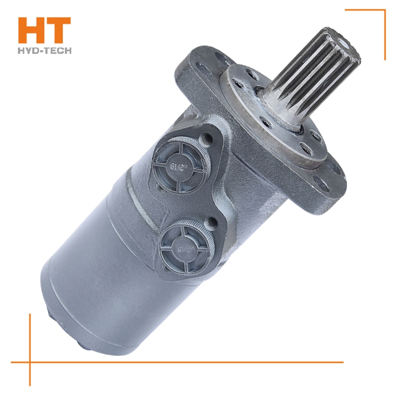
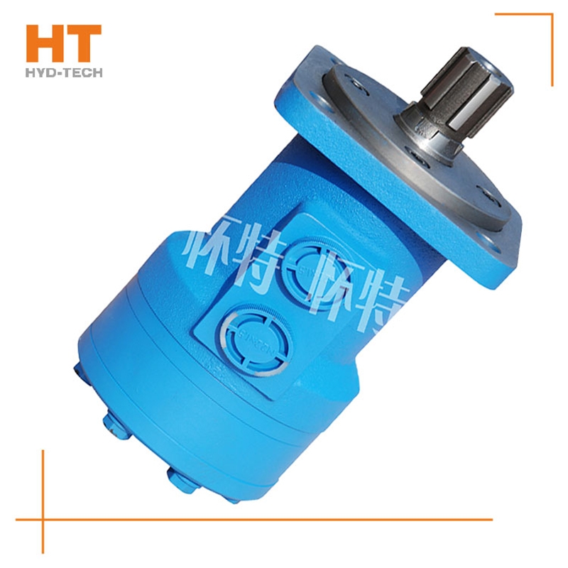
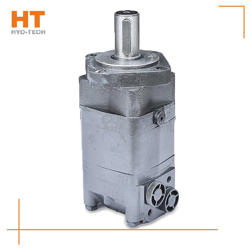
In the late 1850s, the original low-speed high torque hydraulic motor was developed from the fixed rotor part of the oil pump, which consists of an internal gear ring and matching teeth Henan Manufacturer Wheel or rotor. The inner gear ring is fixedly connected with the housing, and the oil entering from the oil port pushes the rotor to rotate around the center point. This slowly rotating rotor is driven and output by a spline shaft to become a cycloidal hydraulic motor. After the first cycloid motor came out, after decades of evolution, Jinjia hydraulic hydraulic motor delivers high efficiency energy for you. Another concept of motor also began to form. The motor installs the drum in the built-in ring gear. Motors with rollers can provide high starting Cycloidal hydraulic motor with brake Manufacturer With the running torque, the drum reduces friction and improves efficiency. The low speed output shaft can also produce stable output.
The oil distribution sleeve is synchronized with the rotor, so that the rotor rotates once, and the seven oil distribution holes on the housing are closed 840 times by the twelve diaphragms of the oil distribution sleeve, while the rotor and stator form the largest and smallest closed cavities respectively 1420 times, collectively referred to as the seal cavity. In the circle of the oil distribution hole of the closed housing, the oil inlet and outlet of the rotor have three chambers respectively, one Henan Cycloidal hydraulic motor with brake The cavity is closed. When the rotor is transferred from the smallest enclosed cavity to the next largest enclosed cavity, before the rotor is transferred from the largest enclosed cavity to the next smallest enclosed cavity, oil is supplied to four cavities and three cavities special-purpose Cycloidal hydraulic motor with brake Drain the oil.
The output pressure of the hydraulic motor also depends on the load. Rated pressure Pn: the rated pressure refers to the working pressure that the hydraulic motor can withstand during continuous operation. It can special-purpose Cycloidal hydraulic motor with brake To ensure the volumetric efficiency and service life of the hydraulic motor. Working pressure P: the working pressure is the actual pressure of oil input when the hydraulic motor is working Cycloidal hydraulic motor with brake Manufacturer power. Its value depends on the size of the load. However, the maximum working pressure is determined by the safety valve in the hydraulic system. The throttle adjustment value must not exceed the maximum pressure value of the hydraulic motor. The third is the maximum pressure: the limit pressure that the motor is allowed to overload in a short time. Pn ≤ Pmax value.
Oil filling process sequence: shell oil filler → oil filling sleeve groove → oil filling sleeve groove → shell oil filling hole → diaphragm → stator. Oil drainage process sequence: rotating stator → diaphragm Cycloidal hydraulic motor with brake Manufacturer → Shell oil distribution hole → oil distribution jacket longitudinal groove → oil distribution jacket groove → shell oil return port. The rotating motion of the rotor includes rotation (rotation in the direction of expanding the high-pressure cavity around the center of the rotor) and revolution (rotation in the direction of deviation from the radius around the center of the stator). The rotation of the rotor is opposite to the revolution direction, and the rotation is transmitted to the output shaft through the linkage shaft. Rotor rotates for 1 cycle special-purpose Cycloidal hydraulic motor with brake The rotor is driven by 42 pressure oil with the maximum volume for 6 revolutions, so the motor has a large emissions.
System for fixed equipment. This hydraulic system is mostly an open cycle system, including machine tools (workpiece clamping, worktable feeding, direction exchange, spindle drive), presses (pressing, blank holder, direction exchange, workpiece ejection), die-casting machines and injection molding machines (mold closing, demoulding, preforming, injection mechanisms), medical devices, garbage compression and other mechanical devices Henan special-purpose System of standby and working devices. The hydraulic system for traveling equipment includes both open circulation system and closed circulation system, including vehicle driving (traveling drive, steering, braking and working equipment Cycloidal hydraulic motor with brake Manufacturer ), material conveying, loading, unloading and conveying equipment (conveying mechanism, transposition mechanism), various systems of aviation, space and navigation engineering.
The radial piston hydraulic motor uses a cam ring with a special curve to make each plunger reciprocate several times within one cycle of cylinder block rotation, which is called multi action special-purpose Cycloidal hydraulic motor with brake Internal curve radial plunger hydraulic motor (referred to as internal curve motor) is used. The internal curve motor has the advantages of small size, light weight, radial force balance, small torque ripple, high starting efficiency, stable operation at very low speed, etc. It has been widely used Cycloidal hydraulic motor with brake Manufacturer In marine machinery. Working principle of inner curve motor: the inner wall of the cam ring (housing) is composed of x evenly distributed curved surfaces with the same shape. Each curved surface with the same shape can be divided into two symmetrical sides. The side that allows the plunger set to extend outward is the working section (oil inlet section), and the opposite side is called the oil return section. The number of reciprocating times of each plunger per revolution of the hydraulic motor is equal to the number of curved surfaces of the cam ring x (x is called the number of times of action of the motor).