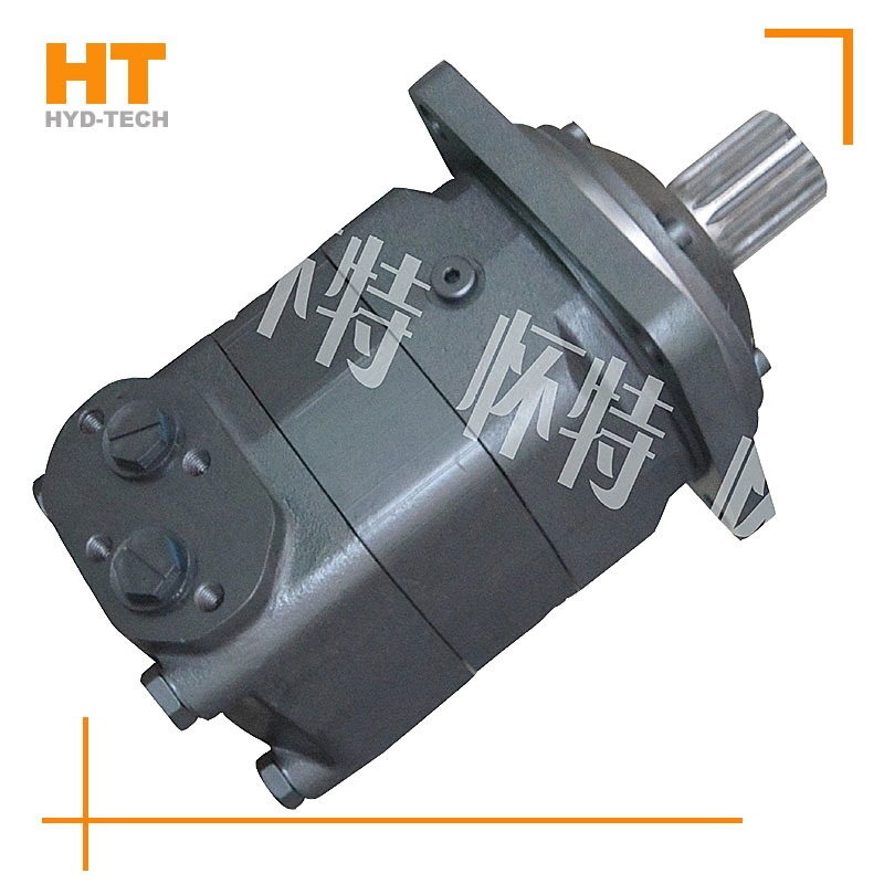
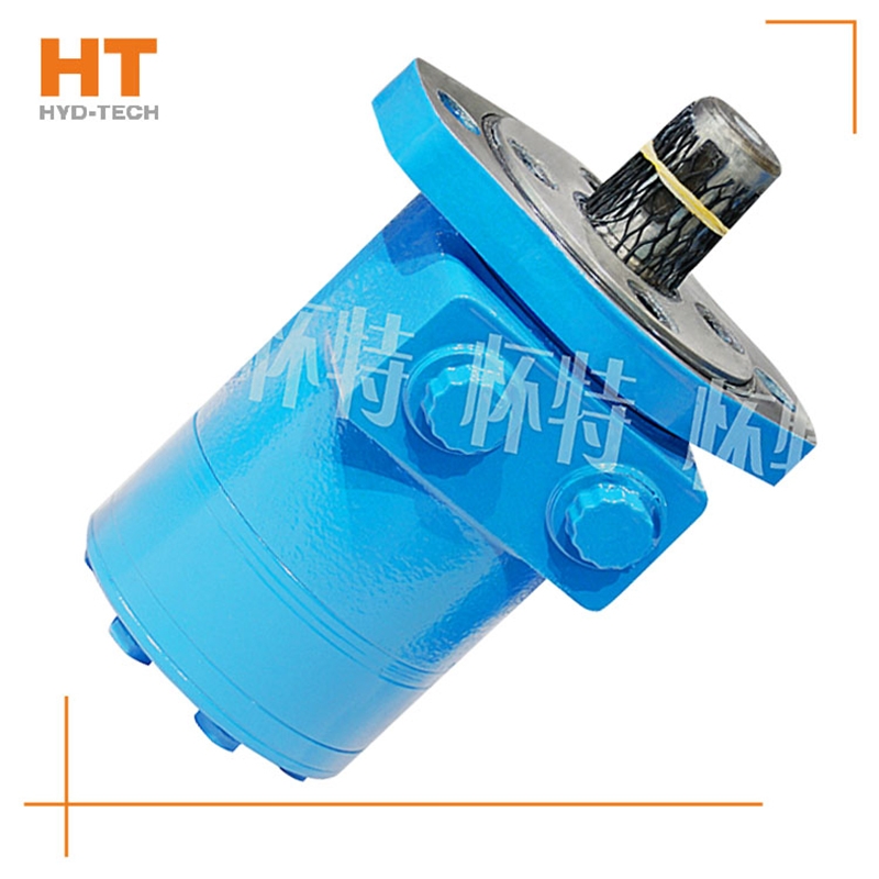
Cycloidal hydraulic motor structure: the internal meshing gear pair consisting of rotor and stator, cycloidal needle wheel, as the meshing pair, has a torque generating part. The stator, together with the spacer and the rear cover, is fixed on the housing to form seven cavities that are only connected with the oil holes on the housing one by one. A distribution mechanism consisting of an oil distribution sleeve and a housing. Two oil distribution sleeves the north sea Cycloidal hydraulic motor with brake The ring groove is respectively connected with the oil inlet and return ports of the housing, and its longitudinal groove has twelve oil ports, Cycloidal hydraulic motor with brake manufactor Six oil ports and the oil distribution hole of the housing form the oil distribution link. The splines at both ends of the linkage shaft are respectively connected with the rotor and the output shaft, which is used to transmit torque and ensure that the oil sleeve is synchronized with the output shaft. The function of the output shaft is to output the torque generated by the rotor through the linkage shaft and drive the oil distribution device to rotate synchronously.
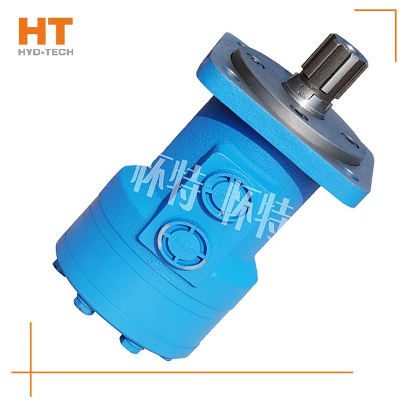
Along the revolution direction of the rotor, the volume of the tooth cavity at the front side of the connection between the rotor and the stator becomes smaller, which is an oil discharge cavity, and the volume at the rear side becomes larger. When the connecting line passes through the two tooth roots of the rotor, the oil inlet ends and the largest tooth cavity appears. When the connecting line passes through the two tooth tops of the rotor, the oil drainage ends and the smallest tooth cavity appears. In order to ensure the continuous rotation of the rotor, it is necessary to have the same regular oil distribution mechanism to cooperate with it, so that the tooth cavity at the front side of the connecting pipeline is always connected with the oil drain port, and the rear side is connected with the oil inlet port. As mentioned above, the oil distribution mechanism consists of a housing and an oil distribution sleeve. The 12 longitudinal grooves (x) on the oil distribution sleeve and the 12 intervals formed by the oil distribution groove face the root and top of the rotor through the positioning device, which proves that when the largest and smallest cavities occur, the oil distribution hole of the housing can be closed, thus separating the oil inlet groove and oil outlet groove of the oil distribution sleeve.
1. The hydraulic system is characterized by high energy density. For motors with the same power, hydraulic motors are much smaller and lighter than motors. And it is easy to apply to mobile devices. 2. The hydraulic motor has convenient speed regulation, which can be adjusted infinitely from 0 to the maximum speed according to the adjustment of the hydraulic valve. The motor itself does not need special design and has low cost. This is much cheaper than motor+reducer, or variable frequency motor and servo motor. 3. The hydraulic motor is totally enclosed and can be safely used in dusty, wet (even underwater) and flammable environments, which is much more reliable than explosion-proof (flameproof) motors. 4. The hydraulic system has strong anti overload capacity, and it is protected by the overflow valve, allowing long (relatively) frequent overloads. It is easy to recover under overload conditions, without damaging the equipment or restarting the equipment. These unparalleled advantages of motors have made hydraulic motors and hydraulic technology rapidly spread and popularized all over the world in the past 20 years. People increasingly feel the importance of hydraulic motors in practice.
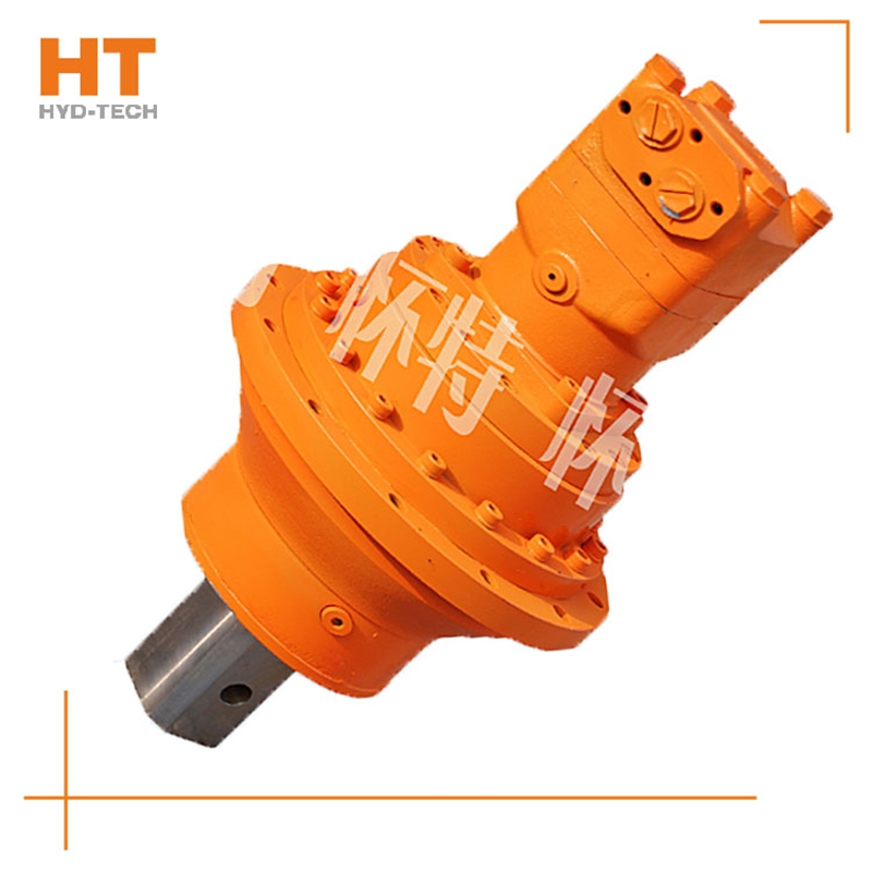
When the high-pressure oil enters the oil distribution shaft and enters each plunger cylinder hole of the working section through the oil distribution window, the corresponding plunger set is pushed against the curved surface of the cam ring L (housing), the north sea Cycloidal hydraulic motor with brake The cam ring surface gives a reaction force to the plunger at the contact position. This reaction force N acts on the common plane where the cam ring surface contacts the roller. This normal reaction force N can be decomposed into radial force PH and circumferential force T, which are balanced with the hydraulic pressure at the bottom of the plunger, while the circumferential force T overcomes the load torque, customized Cycloidal hydraulic motor with brake Drive cylinder 2 to rotate. Under this working condition, the cam ring and oil distribution shaft do not rotate. At this time, the plunger corresponding to the oil return section of the cam gear moves in the opposite direction, and the oil is discharged through the oil distribution shaft.


