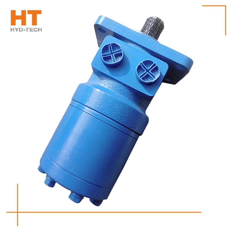
The valve control system controls the flow by changing the opening of the valve throttle, thus controlling the speed of the actuator. Usually, the reason for low efficiency is the existence of throttling and overflow losses. Almost all mechanical equipment adopts valve control system. The pump control system can realize the stepless control of speed by changing the displacement of variable displacement pump, or control the flow through the combination of multiple constant displacement pumps to achieve the stepwise control of speed. The reason for high efficiency is that there is no throttling or overflow loss. It is widely used in high power hydraulic devices such as pressure processing machinery and plastic machinery. The actuator control system controls the flow by changing the variable hydraulic motor flow of the actuator, or through the joint work of multiple quantitative hydraulic motors, or by changing the action area of the composite hydraulic cylinder. Similar to the pump control system, this system has high efficiency because it has no throttling and overflow losses. It is suitable for traveling machinery, press and other hydraulic equipment.
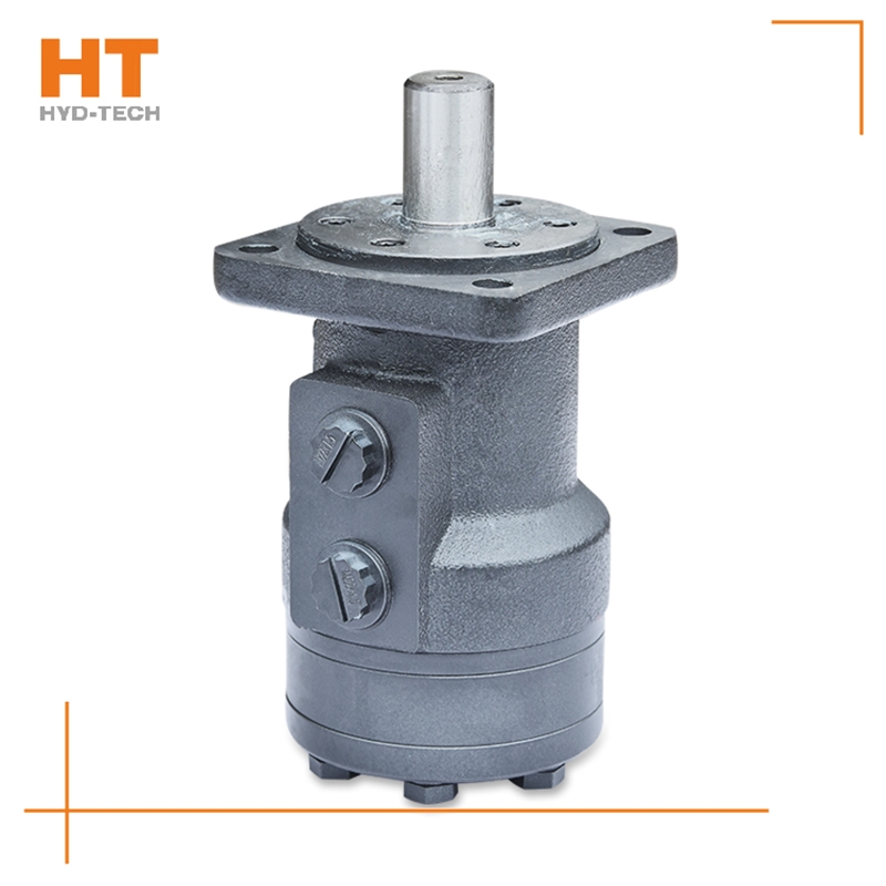
Most of its hydraulic system uses working medium, such as hydraulic oil with continuous fluidity, which converts the mechanical energy of the prime mover driving the pump into the pressure energy of the liquid through the hydraulic pump, and sends it to the actuator (hydraulic cylinder, hydraulic motor or swing hydraulic motor) through various control valves, such as pressure, flow, direction, etc., to convert it into mechanical energy to drive the load. This hydraulic system is generally composed of the following parts: power source, actuator, control valve, hydraulic auxiliary device and hydraulic working medium, which play their respective roles: power source: prime mover (motor or internal combustion engine) and hydraulic pump, whose role is to convert the mechanical energy generated by the prime mover into the pressure energy of liquid, and output oil with a certain pressure;
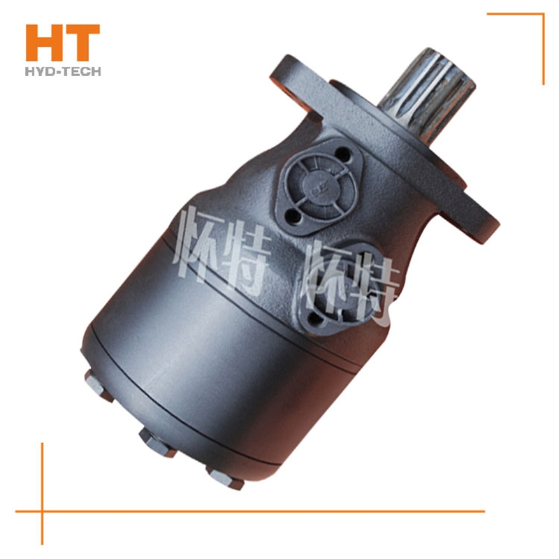
At present, the system used in series by multiple cycloidal motors (see Figure 1) is applied to sweepers, trenchless drills and airport luggage carts. The output shaft of the hydraulic motor often leaks oil during use, so it is useless to replace the dynamic seal of the output shaft. In series application, the problem of casing oil leakage pressure is ignored. The oil leakage pressure of the housing refers to the maximum pressure that the motor shaft seal can bear after the hydraulic motor is fully lubricated inside; If the hydraulic motor is applied want to buy Cycloid hydraulic motor Improper. After the machine has been working continuously for a period of time, due to various factors, the oil in the housing will not be released, resulting in higher and higher pressure in the housing of the hydraulic motor, which first leads to the failure of the shaft seal. The casing leakage pressure mentioned here is not the bursting pressure of the casing, but the pressure that the motor output shaft dynamic seal can bear. In the motor samples of some manufacturers, only the back pressure is mentioned. Actually, back pressure refers to electricity Cycloid hydraulic motor manufactor The return oil pressure of the engine, not the oil discharge pressure of the casing. During operation, the requirements for the oil discharge pressure of the cycloidal motor housing are as follows. Eaton is the world's first cycloid motor manufacturer. In China's domestic cycloidal motor manufacturing industry, Jining Jinjia Hydraulic Co., Ltd. uses Eaton technology to produce cycloidal motors. Its output shaft dynamic seal has better bearing capacity, that is, the unique internal oil circuit design of the company's products enables internal oil drainage not only to lubricate parts, but also to discharge excess oil while maintaining a certain housing oil drainage pressure.
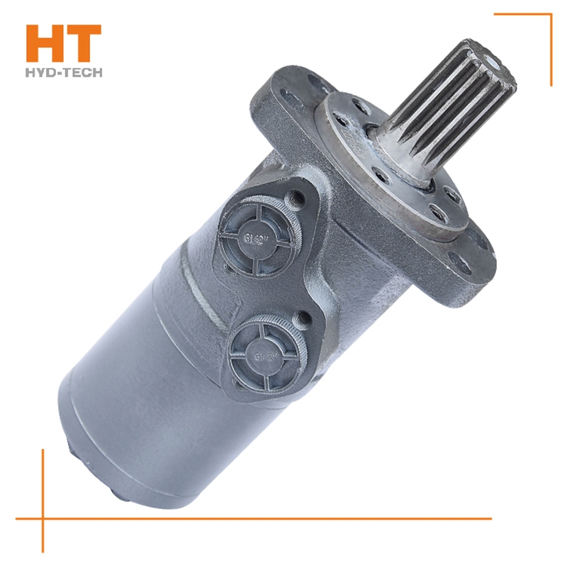
What is the oil supply mode of the hydraulic pump? The straight shaft swashplate plunger pump can be divided into two types: self suction type and pressurized type. Most high-pressure oil supply hydraulic pumps use pneumatic oil tank, and some hydraulic pumps are also equipped with oil make-up slave pump to deliver pressure oil to the oil inlet of the hydraulic pump. The self-priming pump has the characteristics of strong self-priming ability and no need for external oil supply want to buy Cycloid hydraulic motor 。 Bearings for hydraulic pumps. The most important part of the plunger pump is the bearing. If the bearing has clearance, the normal clearance of the three pairs of friction pairs inside the hydraulic pump cannot be guaranteed. At the same time, the hydrostatic support oil film thickness of each friction pair will be damaged, thus reducing the service life of the plunger pump bearing. According to the data provided by the manufacturer of the hydraulic pump, the average service life of the bearing is 10000 hours. If the service life exceeds this value, a new port shall be replaced. 3、 Conclusion. The service life of the piston pump is related to the maintenance at ordinary times, the quantity and quality of the hydraulic oil, and the cleanliness of the oil. At the same time, avoid Cycloid hydraulic motor manufactor The particles in the oil will wear the friction pair of the plunger pump, which is also an effective method to extend its service life.
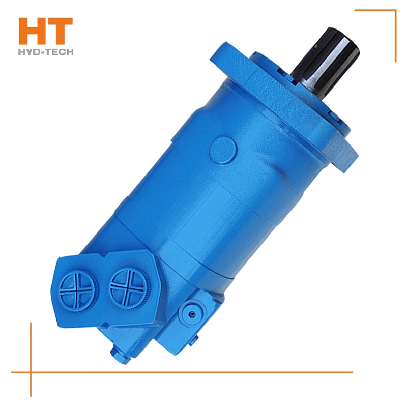
The radial piston hydraulic motor uses a cam ring with a special curve to make each plunger reciprocate several times within one cycle of cylinder block rotation, which is called multi action want to buy Cycloid hydraulic motor Internal curve radial plunger hydraulic motor (referred to as internal curve motor) is used. The internal curve motor has the advantages of small size, light weight, radial force balance, small torque ripple, high starting efficiency, stable operation at very low speed, etc. It has been widely used Cycloid hydraulic motor manufactor In marine machinery. Working principle of inner curve motor: the inner wall of the cam ring (housing) is composed of x evenly distributed curved surfaces with the same shape. Each curved surface with the same shape can be divided into two symmetrical sides. The side that allows the plunger set to extend outward is the working section (oil inlet section), and the opposite side is called the oil return section. The number of reciprocating times of each plunger per revolution of the hydraulic motor is equal to the number of curved surfaces of the cam ring x (x is called the number of times of action of the motor).
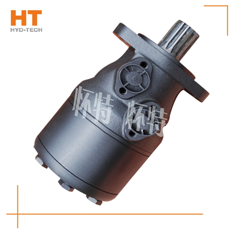
1. Generally, the motor shall be able to run forward and backward. Therefore, the hydraulic motor is usually required to have structural symmetry in the design. 2. The actual working pressure difference of the hydraulic motor depends on the load torque. When the moment of inertia of the driven load is large and the speed is high, rapid braking or reverse rotation is required, high hydraulic impact will be generated. Therefore, the system should be equipped with necessary safety valves and buffer valves. 3. Under normal working conditions, the inlet and outlet pressure of the hydraulic motor is higher than the atmospheric pressure, so there is no suction performance problem like the hydraulic pump. However, if the hydraulic motor can work under pump conditions, its oil inlet should have a minimum pressure limit to avoid cavitation. 4. Some hydraulic motors must have sufficient back pressure at the oil return port to ensure normal operation. The higher the speed, the greater the back pressure, which indicates that the utilization rate of oil source pressure is not high and the system loss is increased. 5. Because the internal leakage of the motor is inevitable, there will be slow sliding when the hydraulic motor oil outlet is closed for braking. Therefore, when long-term accurate braking is required, a separate anti-skid brake shall be set.


![]()

