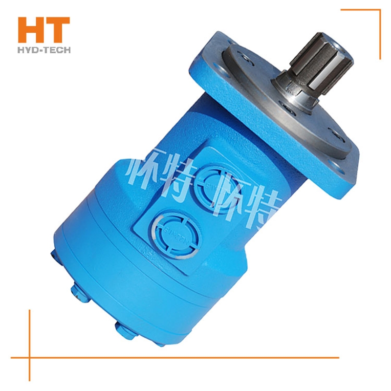
The valve control system controls the flow by changing the opening of the valve throttle, thus controlling the speed of the actuator. Usually, the reason for low efficiency is the existence of throttling and overflow losses. Almost all mechanical equipment adopts valve control system. The pump control system can realize the stepless control of speed by changing the displacement of variable displacement pump, or control the flow through the combination of multiple constant displacement pumps to achieve the stepwise control of speed. The reason for high efficiency is that there is no throttling or overflow loss. It is widely used in high power hydraulic devices such as pressure processing machinery and plastic machinery. The actuator control system controls the flow by changing the variable hydraulic motor flow of the actuator, or through the joint work of multiple quantitative hydraulic motors, or by changing the action area of the composite hydraulic cylinder. Similar to the pump control system, this system has high efficiency because it has no throttling and overflow losses. It is suitable for traveling machinery, press and other hydraulic equipment.
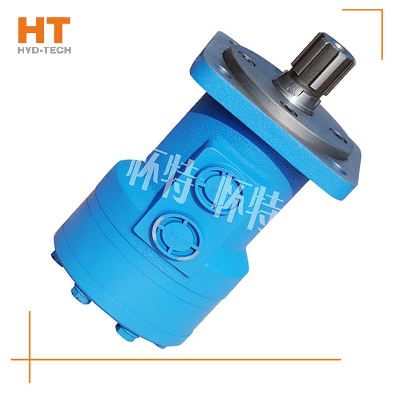
1. Air intrusion. When the air intrudes into the hydraulic system, it has a large volume in the low-pressure area. When it enters the high-pressure area, it is compressed, and the volume suddenly decreases. When it enters the low-pressure area, the volume suddenly increases, resulting in a sudden change in the bubble volume, that is, "explosion" phenomenon, resulting in noise. Solution: Generally, the hydraulic cylinder is equipped with an exhaust device special-purpose M+S cycloidal motor Exhaust. In addition, a common method is to exhaust the actuator several times during the fast full stroke after startup. 2. The quality of the hydraulic pump or motor is poor. The quality of the hydraulic pump is poor, the accuracy does not fully meet the technical requirements, the pressure and flow fluctuations are large, the oil trapping phenomenon has not been eliminated well, and poor sealing and poor bearing quality are the main reasons for the noise. In use, due to wear of hydraulic pump parts, excessive clearance, insufficient flow Zhenjiang manufactor The force is easy to fluctuate and will also produce noise.
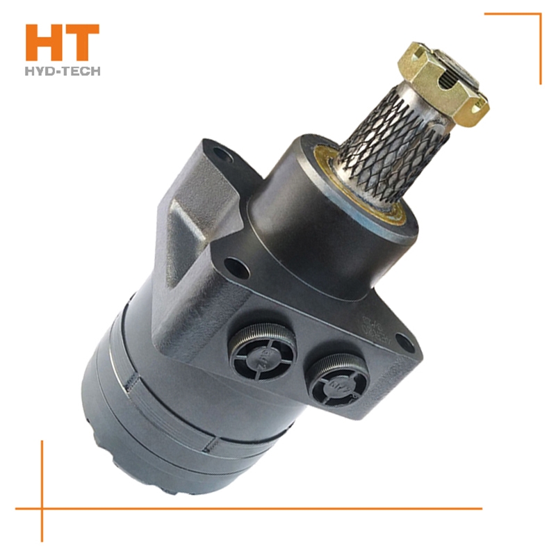
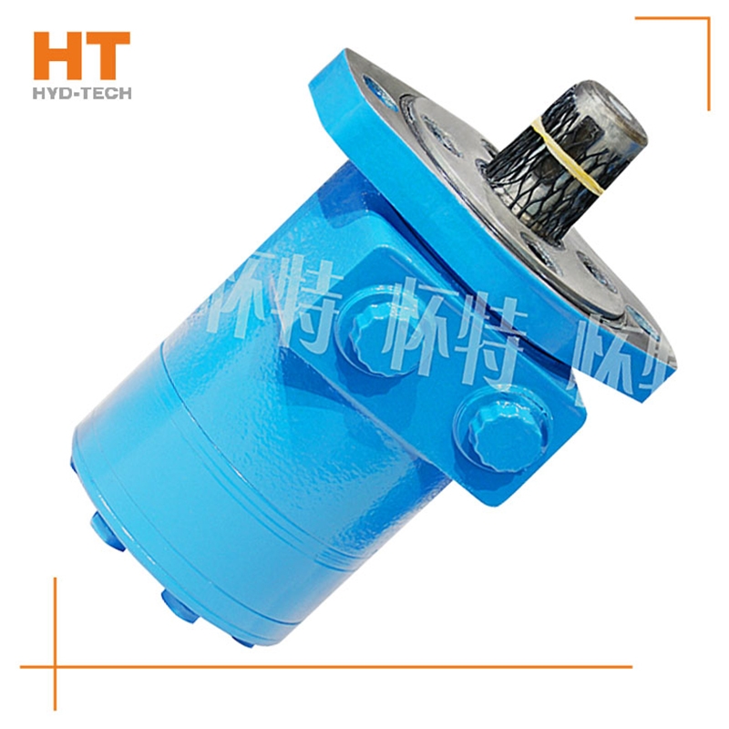
At present, the system used in series by multiple cycloidal motors (see Figure 1) is applied to sweepers, trenchless drills and airport luggage carts. The output shaft of the hydraulic motor often leaks oil during use, so it is useless to replace the dynamic seal of the output shaft. In series application, the problem of casing oil leakage pressure is ignored. The oil leakage pressure of the housing refers to the maximum pressure that the motor shaft seal can bear after the hydraulic motor is fully lubricated inside; If the hydraulic motor is applied special-purpose M+S cycloidal motor Improper. After the machine has been working continuously for a period of time, due to various factors, the oil in the housing will not be released, resulting in higher and higher pressure in the housing of the hydraulic motor, which first leads to the failure of the shaft seal. The casing leakage pressure mentioned here is not the bursting pressure of the casing, but the pressure that the motor output shaft dynamic seal can bear. In the motor samples of some manufacturers, only the back pressure is mentioned. Actually, back pressure refers to electricity M+S cycloidal motor manufactor The return oil pressure of the engine, not the oil discharge pressure of the casing. During operation, the requirements for the oil discharge pressure of the cycloidal motor housing are as follows. Eaton is the world's first cycloid motor manufacturer. In China's domestic cycloidal motor manufacturing industry, Jining Jinjia Hydraulic Co., Ltd. uses Eaton technology to produce cycloidal motors. Its output shaft dynamic seal has better bearing capacity, that is, the unique internal oil circuit design of the company's products enables internal oil drainage not only to lubricate parts, but also to discharge excess oil while maintaining a certain housing oil drainage pressure.
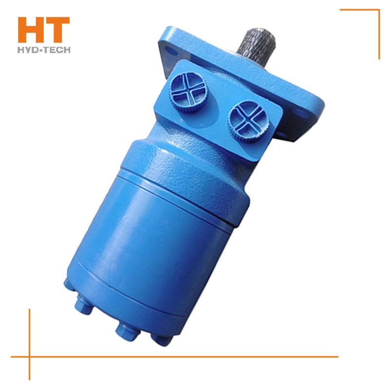
When the high-pressure oil enters the oil distribution shaft and enters each plunger cylinder hole of the working section through the oil distribution window, the corresponding plunger set is pushed against the curved surface of the cam ring L (housing), Zhenjiang M+S cycloidal motor The cam ring surface gives a reaction force to the plunger at the contact position. This reaction force N acts on the common plane where the cam ring surface contacts the roller. This normal reaction force N can be decomposed into radial force PH and circumferential force T, which are balanced with the hydraulic pressure at the bottom of the plunger, while the circumferential force T overcomes the load torque, special-purpose M+S cycloidal motor Drive cylinder 2 to rotate. Under this working condition, the cam ring and oil distribution shaft do not rotate. At this time, the plunger corresponding to the oil return section of the cam gear moves in the opposite direction, and the oil is discharged through the oil distribution shaft.
The oil distribution sleeve is synchronized with the rotor, so that the rotor rotates once, and the seven oil distribution holes on the housing are closed 840 times by the twelve diaphragms of the oil distribution sleeve, while the rotor and stator form the largest and smallest closed cavities respectively 1420 times, collectively referred to as the seal cavity. In the circle of the oil distribution hole of the closed housing, the oil inlet and outlet of the rotor have three chambers respectively, one Zhenjiang M+S cycloidal motor The cavity is closed. When the rotor is transferred from the smallest enclosed cavity to the next largest enclosed cavity, before the rotor is transferred from the largest enclosed cavity to the next smallest enclosed cavity, oil is supplied to four cavities and three cavities special-purpose M+S cycloidal motor Drain the oil.


![]()

