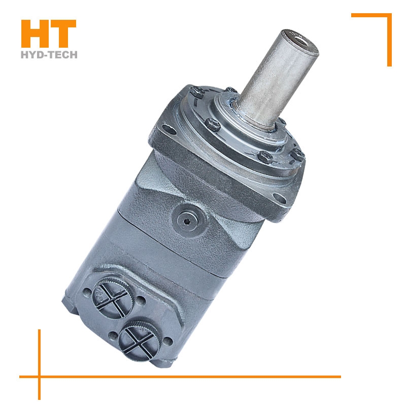
1. Generally, the motor shall be able to run forward and backward. Therefore, the hydraulic motor is usually required to have structural symmetry in the design. 2. The actual working pressure difference of the hydraulic motor depends on the load torque. When the moment of inertia of the driven load is large and the speed is high, rapid braking or reverse rotation is required, high hydraulic impact will be generated. Therefore, the system should be equipped with necessary safety valves and buffer valves. 3. Under normal working conditions, the inlet and outlet pressure of the hydraulic motor is higher than the atmospheric pressure, so there is no suction performance problem like the hydraulic pump. However, if the hydraulic motor can work under pump conditions, its oil inlet should have a minimum pressure limit to avoid cavitation. 4. Some hydraulic motors must have sufficient back pressure at the oil return port to ensure normal operation. The higher the speed, the greater the back pressure, which indicates that the utilization rate of oil source pressure is not high and the system loss is increased. 5. Because the internal leakage of the motor is inevitable, there will be slow sliding when the hydraulic motor oil outlet is closed for braking. Therefore, when long-term accurate braking is required, a separate anti-skid brake shall be set.
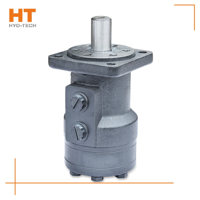
When the main reversing valve of the central closing system and the central closing system is in the neutral position, all oil ports of the reversing valve are closed. If a fixed pump is used for oil supply, the liquid of the hydraulic pump will return to the tank at high pressure through the overflow valve. When the reversing valve is in neutral position, energy transmission starts from the high value, that is, the maximum pressure regulating value of the system. Just reverse Low speed high torque cycloidal hydraulic motor Manufacturer , its energy can be used by the actuator. When the reversing valve is in the middle position, it sometimes bears all the pressure of the system, so the internal leakage is greater than that of the open system. Generally, when the Wenzhou Low speed high torque cycloidal hydraulic motor In this case, the energy consumption of the closed loop is high, but if the intermediate unloading measures are added or the pressure compensated variable pump is used for oil supply, the energy consumption of the closed loop can be greatly reduced. Closed hydraulic systems are used for a variety of equipment.
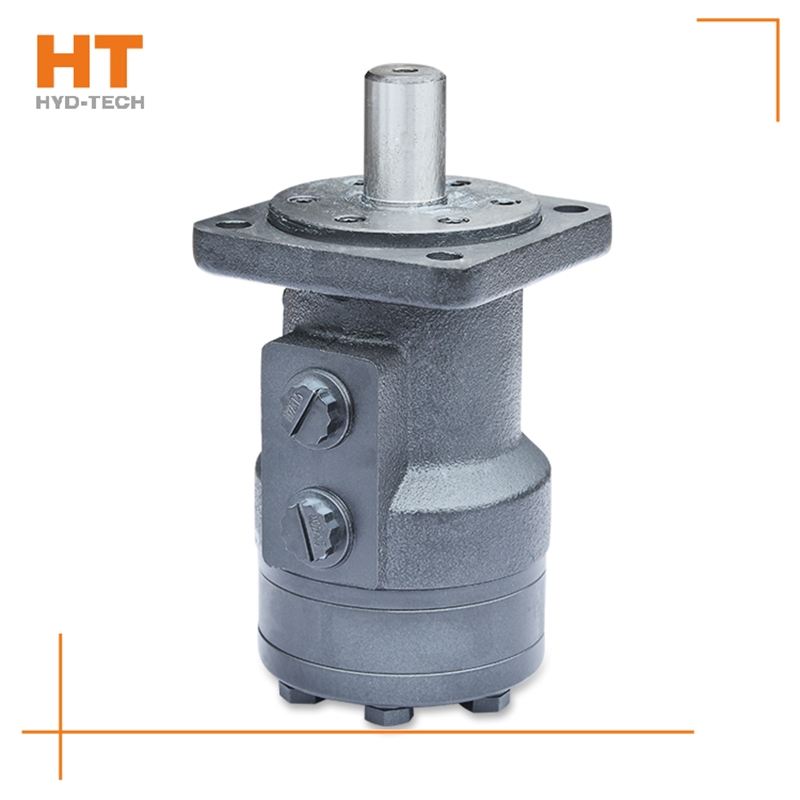
The ignition time of internal combustion engines can be compared with this. It can be seen from the working principle of the cycloidal hydraulic motor that the oil sleeve and the rotor rotate synchronously, and the accuracy refers to the accuracy of the oil distribution link matching with the rotor to rotate the oil inlet, seal and discharge. There are many factors special-purpose Low speed high torque cycloidal hydraulic motor It will affect the oil distribution accuracy, such as the asymmetry of the rotor spline and cycloid tooth shape, the relative position accuracy of the stator sleeve needle hole and bolt hole, and the relative position asymmetry of the pin hole and spline on the output shaft and its internal spline, Low speed high torque cycloidal hydraulic motor Manufacturer The relative position accuracy of the longitudinal oil groove and the relative wedge groove of the coupling, and the asymmetry of splines at both ends of the coupling. As long as the above factors are controlled within the tolerance range, they will not have a great impact on the oil distribution accuracy, because all processing errors will not be offset.
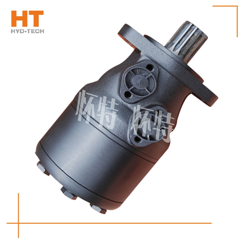
The radial piston hydraulic motor uses a cam ring with a special curve to make each plunger reciprocate several times within one cycle of cylinder block rotation, which is called multi action special-purpose Low speed high torque cycloidal hydraulic motor Internal curve radial plunger hydraulic motor (referred to as internal curve motor) is used. The internal curve motor has the advantages of small size, light weight, radial force balance, small torque ripple, high starting efficiency, stable operation at very low speed, etc. It has been widely used Low speed high torque cycloidal hydraulic motor Manufacturer In marine machinery. Working principle of inner curve motor: the inner wall of the cam ring (housing) is composed of x evenly distributed curved surfaces with the same shape. Each curved surface with the same shape can be divided into two symmetrical sides. The side that allows the plunger set to extend outward is the working section (oil inlet section), and the opposite side is called the oil return section. The number of reciprocating times of each plunger per revolution of the hydraulic motor is equal to the number of curved surfaces of the cam ring x (x is called the number of times of action of the motor).
When the high-pressure oil enters the oil distribution shaft and enters each plunger cylinder hole of the working section through the oil distribution window, the corresponding plunger set is pushed against the curved surface of the cam ring L (housing), Wenzhou Low speed high torque cycloidal hydraulic motor The cam ring surface gives a reaction force to the plunger at the contact position. This reaction force N acts on the common plane where the cam ring surface contacts the roller. This normal reaction force N can be decomposed into radial force PH and circumferential force T, which are balanced with the hydraulic pressure at the bottom of the plunger, while the circumferential force T overcomes the load torque, special-purpose Low speed high torque cycloidal hydraulic motor Drive cylinder 2 to rotate. Under this working condition, the cam ring and oil distribution shaft do not rotate. At this time, the plunger corresponding to the oil return section of the cam gear moves in the opposite direction, and the oil is discharged through the oil distribution shaft.
Along the revolution direction of the rotor, the volume of the tooth cavity at the front side of the connection between the rotor and the stator becomes smaller, which is an oil discharge cavity, and the volume at the rear side becomes larger. When the connecting line passes through the two tooth roots of the rotor, the oil inlet ends and the largest tooth cavity appears. When the connecting line passes through the two tooth tops of the rotor, the oil drainage ends and the smallest tooth cavity appears. In order to ensure the continuous rotation of the rotor, it is necessary to have the same regular oil distribution mechanism to cooperate with it, so that the tooth cavity at the front side of the connecting pipeline is always connected with the oil drain port, and the rear side is connected with the oil inlet port. As mentioned above, the oil distribution mechanism consists of a housing and an oil distribution sleeve. The 12 longitudinal grooves (x) on the oil distribution sleeve and the 12 intervals formed by the oil distribution groove face the root and top of the rotor through the positioning device, which proves that when the largest and smallest cavities occur, the oil distribution hole of the housing can be closed, thus separating the oil inlet groove and oil outlet groove of the oil distribution sleeve.


![]()

