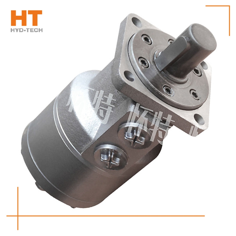
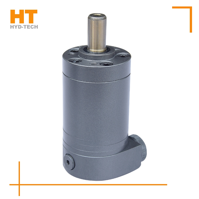
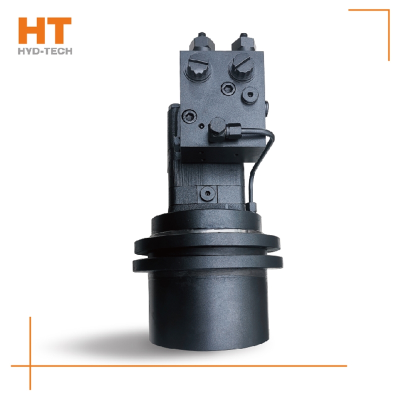
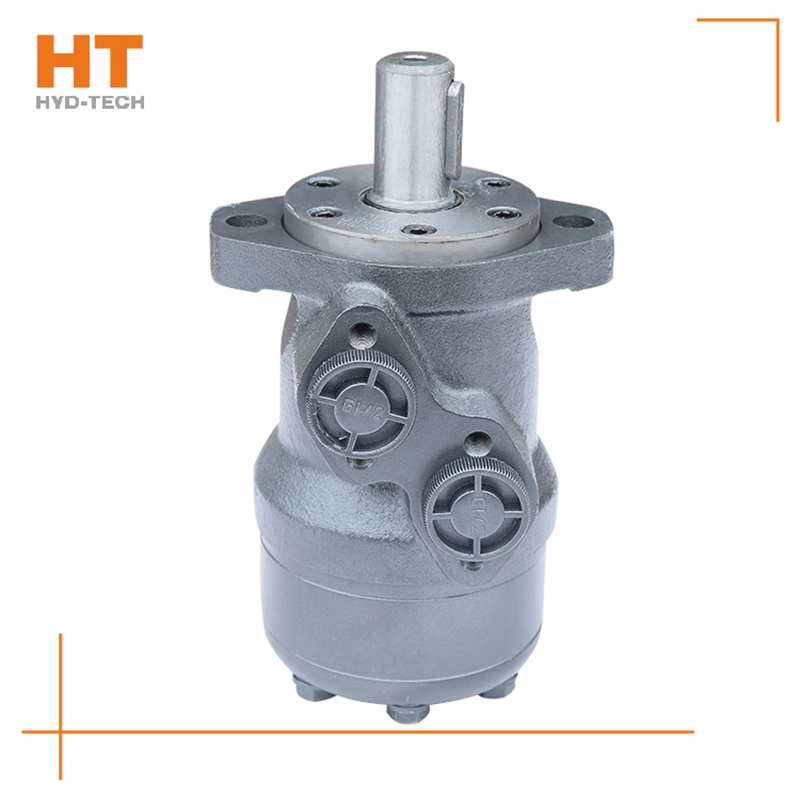
Most of its hydraulic system uses working medium, such as hydraulic oil with continuous fluidity, which converts the mechanical energy of the prime mover driving the pump into the pressure energy of the liquid through the hydraulic pump, and sends it to the actuator (hydraulic cylinder, hydraulic motor or swing hydraulic motor) through various control valves, such as pressure, flow, direction, etc., to convert it into mechanical energy to drive the load. This hydraulic system is generally composed of the following parts: power source, actuator, control valve, hydraulic auxiliary device and hydraulic working medium, which play their respective roles: power source: prime mover (motor or internal combustion engine) and hydraulic pump, whose role is to convert the mechanical energy generated by the prime mover into the pressure energy of liquid, and output oil with a certain pressure;

As a hydraulic equipment, hydraulic motor has been widely used in many factories. Generally, we should master the assembly skills of the hydraulic motor: the hydraulic system should special-purpose Large torque cycloidal motor Correct machining and assembly. The mounting surface of the hydraulic valve on the oil block should be straight, and the sealing surface of the sealing groove should be finished to avoid radial scratches. The preload of the connection between the hydraulic valve and the oil circuit block and the connection between the oil circuit blocks shall be sufficient to prevent surface separation. The hydraulic equipment shall be inspected according to relevant standards before assembly Large torque cycloidal motor Manufacturer Check the pressure leakage of system components. If problems are found, corresponding measures shall be taken. If the problem is serious, it should be replaced. Accurately formulate the assembly process documents of hydraulic equipment, configure necessary assembly tools, and strictly follow the assembly process. Keep the hydraulic components, accessories, sealing parts and pipe fittings clean to prevent contamination, and check the integrity of the sealing surface and connecting threads. The hydraulic connector should not be tightened too tightly, otherwise some parts will be severely deformed or even broken, causing leakage. Avoid damaging sealing parts during assembly.

The hydraulic motor has two circuits: the hydraulic motor series circuit and the hydraulic motor braking circuit. These two circuits can be classified into the next category. One of the series circuits of hydraulic motors: three hydraulic motors are connected in series with each other, and a reversing valve is used to control the start stop and steering. The flow through the three motors is basically the same. When the displacement is the same, the speed of each motor is basically the same. The oil supply pressure of the hydraulic pump Xingtai Manufacturer High, small pump flow, generally used for light load and high speed. Serial circuit II of hydraulic motor: each reversing valve in this circuit controls one motor, each motor can work independently or simultaneously, and the rotation direction of each motor is also special-purpose Large torque cycloidal motor optional. The oil supply pressure of the hydraulic pump is the sum of the working pressure difference of each motor, which is applicable to the condition of high speed and small torque.

Along the revolution direction of the rotor, the volume of the tooth cavity at the front side of the connection between the rotor and the stator becomes smaller, which is an oil discharge cavity, and the volume at the rear side becomes larger. When the connecting line passes through the two tooth roots of the rotor, the oil inlet ends and the largest tooth cavity appears. When the connecting line passes through the two tooth tops of the rotor, the oil drainage ends and the smallest tooth cavity appears. In order to ensure the continuous rotation of the rotor, it is necessary to have the same regular oil distribution mechanism to cooperate with it, so that the tooth cavity at the front side of the connecting pipeline is always connected with the oil drain port, and the rear side is connected with the oil inlet port. As mentioned above, the oil distribution mechanism consists of a housing and an oil distribution sleeve. The 12 longitudinal grooves (x) on the oil distribution sleeve and the 12 intervals formed by the oil distribution groove face the root and top of the rotor through the positioning device, which proves that when the largest and smallest cavities occur, the oil distribution hole of the housing can be closed, thus separating the oil inlet groove and oil outlet groove of the oil distribution sleeve.


![]()

