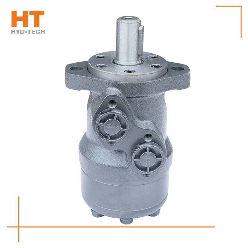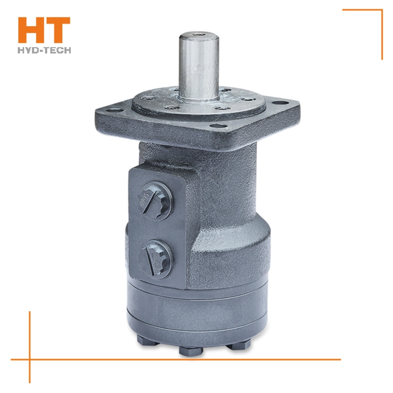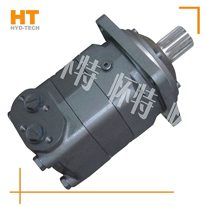
The valve control system controls the flow by changing the opening of the valve throttle, thus controlling the speed of the actuator. Usually, the reason for low efficiency is the existence of throttling and overflow losses. Almost all mechanical equipment adopts valve control system. The pump control system can realize the stepless control of speed by changing the displacement of variable displacement pump, or control the flow through the combination of multiple constant displacement pumps to achieve the stepwise control of speed. The reason for high efficiency is that there is no throttling or overflow loss. It is widely used in high power hydraulic devices such as pressure processing machinery and plastic machinery. The actuator control system controls the flow by changing the variable hydraulic motor flow of the actuator, or through the joint work of multiple quantitative hydraulic motors, or by changing the action area of the composite hydraulic cylinder. Similar to the pump control system, this system has high efficiency because it has no throttling and overflow losses. It is suitable for traveling machinery, press and other hydraulic equipment.

1. Generally, the motor shall be able to run forward and backward. Therefore, the hydraulic motor is usually required to have structural symmetry in the design. 2. The actual working pressure difference of the hydraulic motor depends on the load torque. When the moment of inertia of the driven load is large and the speed is high, rapid braking or reverse rotation is required, high hydraulic impact will be generated. Therefore, the system should be equipped with necessary safety valves and buffer valves. 3. Under normal working conditions, the inlet and outlet pressure of the hydraulic motor is higher than the atmospheric pressure, so there is no suction performance problem like the hydraulic pump. However, if the hydraulic motor can work under pump conditions, its oil inlet should have a minimum pressure limit to avoid cavitation. 4. Some hydraulic motors must have sufficient back pressure at the oil return port to ensure normal operation. The higher the speed, the greater the back pressure, which indicates that the utilization rate of oil source pressure is not high and the system loss is increased. 5. Because the internal leakage of the motor is inevitable, there will be slow sliding when the hydraulic motor oil outlet is closed for braking. Therefore, when long-term accurate braking is required, a separate anti-skid brake shall be set.

In order to meet the needs of national economic development, hydraulic technology will continue to develop rapidly and be widely used in various industrial sectors. Therefore, vigorously developing the hydraulic machinery industry is also special-purpose Danfoss cycloid motor In order to revitalize the development of the machinery industry. Based on improving the technical level of basic parts, we will increase the strength of technological innovation, supplemented by policy support, and fundamentally improve the technical level to achieve industrial development. On the other hand, it also shows that the development of hydraulic press in China has entered a new stage, and the development level of heavy equipment represents Danfoss cycloid motor Manufacturer The engineering technology level of a country. Therefore, in general, the prospect of hydraulic press in China will be better and better.

Oil filling process sequence: shell oil filler → oil filling sleeve groove → oil filling sleeve groove → shell oil filling hole → diaphragm → stator. Oil drainage process sequence: rotating stator → diaphragm Danfoss cycloid motor Manufacturer → Shell oil distribution hole → oil distribution jacket longitudinal groove → oil distribution jacket groove → shell oil return port. The rotating motion of the rotor includes rotation (rotation in the direction of expanding the high-pressure cavity around the center of the rotor) and revolution (rotation in the direction of deviation from the radius around the center of the stator). The rotation of the rotor is opposite to the revolution direction, and the rotation is transmitted to the output shaft through the linkage shaft. Rotor rotates for 1 cycle special-purpose Danfoss cycloid motor The rotor is driven by 42 pressure oil with the maximum volume for 6 revolutions, so the motor has a large emissions.


![]()

