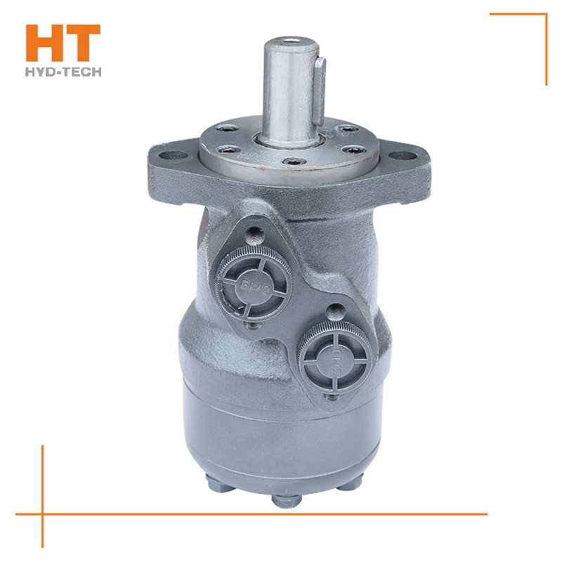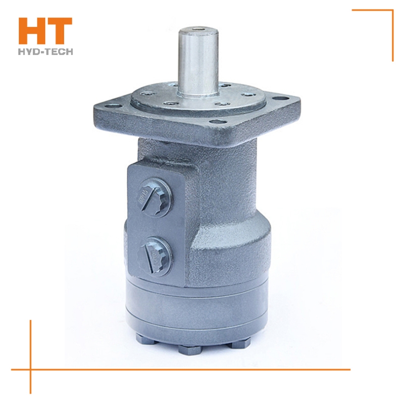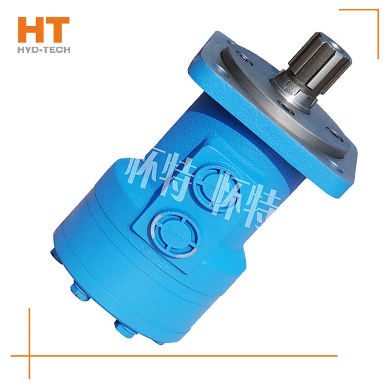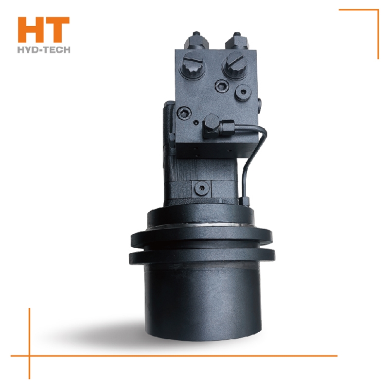
The hydraulic motor manufacturer explains to you the reasons for the poor performance of the hydraulic motor: 1. First of all, according to the analysis of the causes of the wear of the port plate, the main reasons for the weakness of the hydraulic motor are: because the port plate is worn, the oil inlet channel and the oil return channel are connected at the port plate, part of the high-pressure oil leaks, the oil pressure flowing through the stator and rotor pair decreases, and the flow decreases, Eventually, the output speed and torque of the motor will decrease. 2. Due to the wear of the valve plate, its relative position in the valve body has changed BM cycloid motor manufactor The preload and adhesion of the spring on the valve body between the valve plates will be reduced, which will intensify the leakage of hydraulic oil and lead to the decline of the performance of the hydraulic motor. 3. With the increase of hydraulic oil temperature, its comprehensive performance declines, driving the cycloidal rotor to rotate Guangdong manufactor The ability to move is further reduced. Upon inspection, there is no obvious wear on the joint surface of the stator and rotor pair and the bearing seat and valve disc matched with both sides of the stator and rotor pair. The movement is normal without jamming, which will not cause performance degradation.

Causes: 1. The pump is damaged, and the pump body is overheated and produces noise. 2. The control valve is closed tightly or the oil supply and return system is blocked, and local overheating occurs. 3. The safety valve is opened, and the valve cries or hisses, and local overheating occurs. 4. The distribution rotary valve is excessively leaking, and the valve chamber is overheated, and it is very hot when touched by hand. 5. The hydraulic motor crankcase is excessively leaking, and the single oil drain pipe is leaking customized BM cycloid motor Treatment method for excessive leakage and high oil level: 1. Check the condition of the ball joint 2. Check the sealing condition of the cylinder piston 3. Check the viscosity and operating temperature of the oil 4. Check the contact surface between the oil pan and the housing 5. Check the surface between the connecting rod and the eccentric wheel BM cycloid motor manufactor 6. Check the wear of the oil pan and whether the two oil cavity channels at the inlet and outlet of the casting are connected

Of course, you can increase the traffic customized BM cycloid motor Increase the speed, but how much will affect the service life. As long as it is within the rated power range, there is no problem. If the oil pressure reaches the rated pressure and the speed increases, it will exceed the power range it can withstand. Of course, it will damage the service life of the cycloidal hydraulic motor. Just like not eating so much hard food, it will damage the stomach. Increasing the flow can only increase the speed in a limited way, from 500 to 900, change the model of the motor, increase the flow of the cycloidal motor, increase the speed without control, increase the internal oil pressure, increase the internal leakage, directly reduce the efficiency, and damage the motor. Above Guangdong manufactor Ming can try, and consult the cycloid hydraulic motor expert if he thinks the error is found.

Along the revolution direction of the rotor, the volume of the tooth cavity at the front side of the connection between the rotor and the stator becomes smaller, which is an oil discharge cavity, and the volume at the rear side becomes larger. When the connecting line passes through the two tooth roots of the rotor, the oil inlet ends and the largest tooth cavity appears. When the connecting line passes through the two tooth tops of the rotor, the oil drainage ends and the smallest tooth cavity appears. In order to ensure the continuous rotation of the rotor, it is necessary to have the same regular oil distribution mechanism to cooperate with it, so that the tooth cavity at the front side of the connecting pipeline is always connected with the oil drain port, and the rear side is connected with the oil inlet port. As mentioned above, the oil distribution mechanism consists of a housing and an oil distribution sleeve. The 12 longitudinal grooves (x) on the oil distribution sleeve and the 12 intervals formed by the oil distribution groove face the root and top of the rotor through the positioning device, which proves that when the largest and smallest cavities occur, the oil distribution hole of the housing can be closed, thus separating the oil inlet groove and oil outlet groove of the oil distribution sleeve.


![]()

