Along the revolution direction of the rotor, the volume of the tooth cavity at the front side of the connection between the rotor and the stator becomes smaller, which is an oil discharge cavity, and the volume at the rear side becomes larger. When the connecting line passes through the two tooth roots of the rotor, the oil inlet ends and the largest tooth cavity appears. When the connecting line passes through the two tooth tops of the rotor, the oil drainage ends and the smallest tooth cavity appears. In order to ensure the continuous rotation of the rotor, it is necessary to have the same regular oil distribution mechanism to cooperate with it, so that the tooth cavity at the front side of the connecting pipeline is always connected with the oil drain port, and the rear side is connected with the oil inlet port. As mentioned above, the oil distribution mechanism consists of a housing and an oil distribution sleeve. The 12 longitudinal grooves (x) on the oil distribution sleeve and the 12 intervals formed by the oil distribution groove face the root and top of the rotor through the positioning device, which proves that when the largest and smallest cavities occur, the oil distribution hole of the housing can be closed, thus separating the oil inlet groove and oil outlet groove of the oil distribution sleeve.
The valve control system controls the flow by changing the opening of the valve throttle, thus controlling the speed of the actuator. Usually, the reason for low efficiency is the existence of throttling and overflow losses. Almost all mechanical equipment adopts valve control system. The pump control system can realize the stepless control of speed by changing the displacement of variable displacement pump, or control the flow through the combination of multiple constant displacement pumps to achieve the stepwise control of speed. The reason for high efficiency is that there is no throttling or overflow loss. It is widely used in high power hydraulic devices such as pressure processing machinery and plastic machinery. The actuator control system controls the flow by changing the variable hydraulic motor flow of the actuator, or through the joint work of multiple quantitative hydraulic motors, or by changing the action area of the composite hydraulic cylinder. Similar to the pump control system, this system has high efficiency because it has no throttling and overflow losses. It is suitable for traveling machinery, press and other hydraulic equipment.
During the operation of hydraulic transmission, the hydraulic actuator can be adjusted steplessly in a large range by adjusting the control valve, and the speed range can reach 2000 meters. Good operation ability and rapidity. The liquid is elastic and can absorb impact, so the hydraulic transmission movement is even and stable; It is easy to realize fast starting, braking and frequent reversing. Reciprocating rotation customized Sweeper cycloidal hydraulic motor The reversing frequency of rotary motion can reach 500 times/minute, and the reciprocating linear motion can reach 1000 times/minute. It is easy to control operation and realize overload protection. The hydraulic system with convenient operation and control is convenient for automatic control, remote control and overload protection; Automatic lubrication during operation, which is beneficial to Lianyungang Manufacturer Heat dissipation, prolong service life. It is convenient for automation and electromechanical hydraulic integration. Hydraulic technology is easy to combine with electric control and electric control technology to form an electromechanical hydraulic integration composite system to realize automatic cycle work.
Oil filling process sequence: shell oil filler → oil filling sleeve groove → oil filling sleeve groove → shell oil filling hole → diaphragm → stator. Oil drainage process sequence: rotating stator → diaphragm Sweeper cycloidal hydraulic motor Manufacturer → Shell oil distribution hole → oil distribution jacket longitudinal groove → oil distribution jacket groove → shell oil return port. The rotating motion of the rotor includes rotation (rotation in the direction of expanding the high-pressure cavity around the center of the rotor) and revolution (rotation in the direction of deviation from the radius around the center of the stator). The rotation of the rotor is opposite to the revolution direction, and the rotation is transmitted to the output shaft through the linkage shaft. Rotor rotates for 1 cycle customized Sweeper cycloidal hydraulic motor The rotor is driven by 42 pressure oil with the maximum volume for 6 revolutions, so the motor has a large emissions.
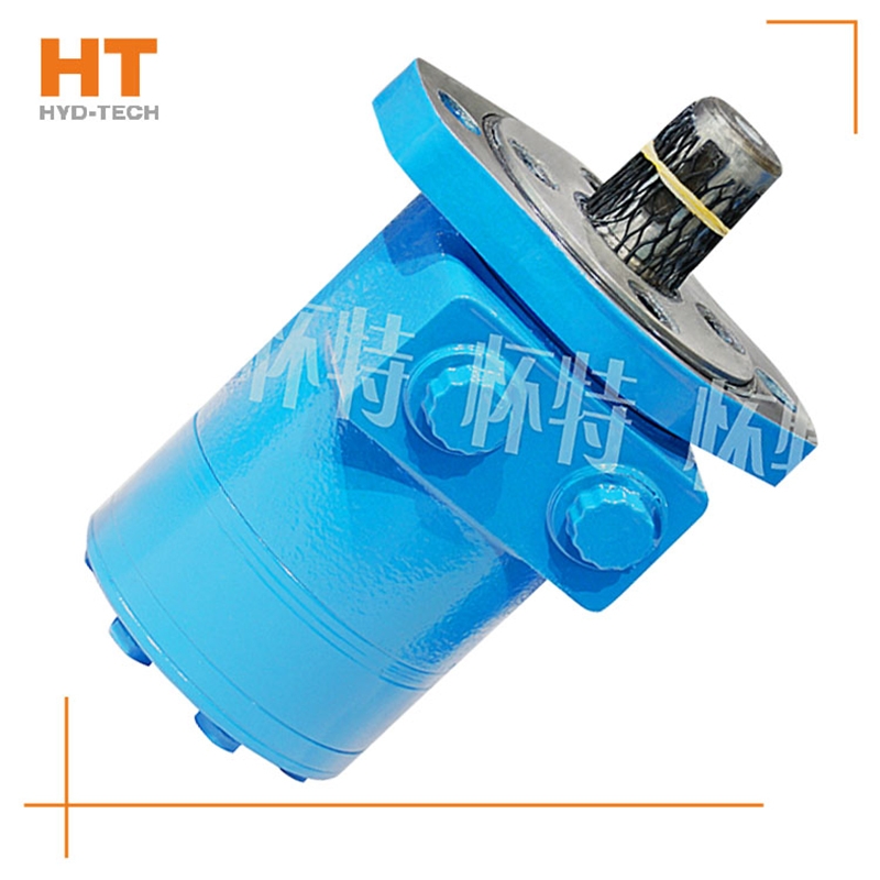
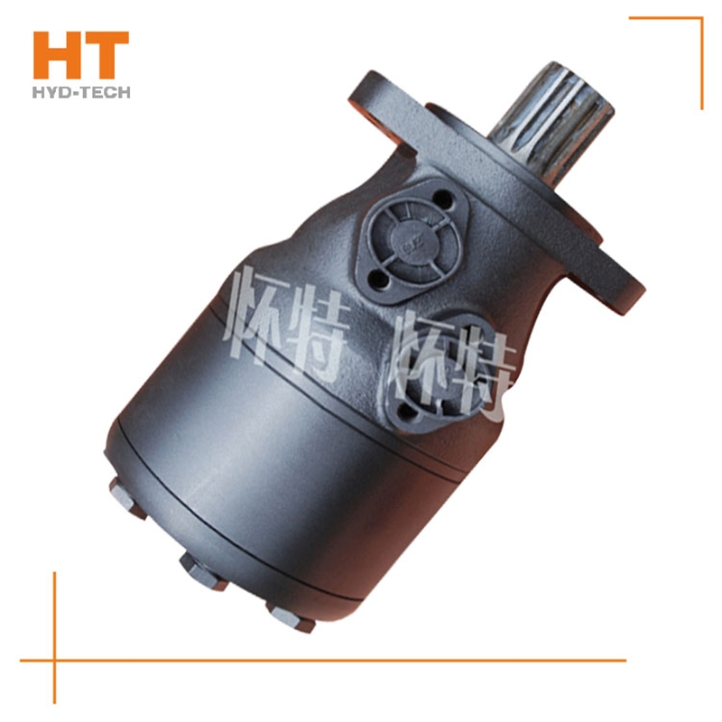
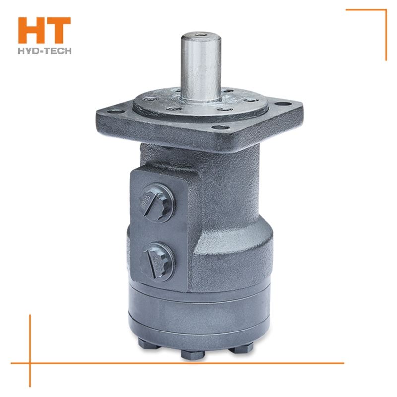
Cycloidal hydraulic motor structure: the internal meshing gear pair consisting of rotor and stator, cycloidal needle wheel, as the meshing pair, has a torque generating part. The stator, together with the spacer and the rear cover, is fixed on the housing to form seven cavities that are only connected with the oil holes on the housing one by one. A distribution mechanism consisting of an oil distribution sleeve and a housing. Two oil distribution sleeves Lianyungang Sweeper cycloidal hydraulic motor The ring groove is respectively connected with the oil inlet and return ports of the housing, and its longitudinal groove has twelve oil ports, Sweeper cycloidal hydraulic motor Manufacturer Six oil ports and the oil distribution hole of the housing form the oil distribution link. The splines at both ends of the linkage shaft are respectively connected with the rotor and the output shaft, which is used to transmit torque and ensure that the oil sleeve is synchronized with the output shaft. The function of the output shaft is to output the torque generated by the rotor through the linkage shaft and drive the oil distribution device to rotate synchronously.


