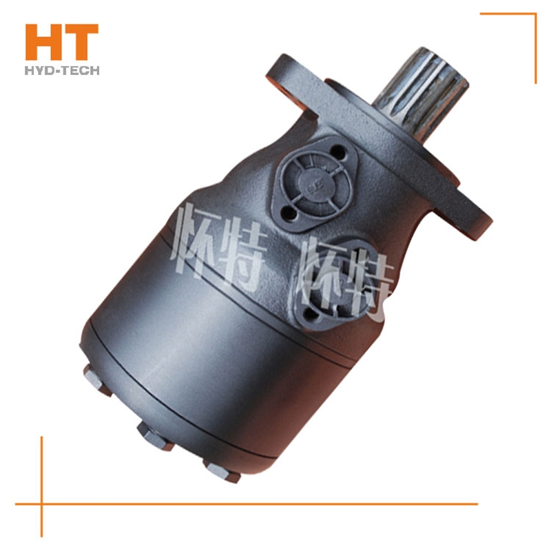
Cycloidal hydraulic motor structure: the internal meshing gear pair consisting of rotor and stator, cycloidal needle wheel, as the meshing pair, has a torque generating part. The stator, together with the spacer and the rear cover, is fixed on the housing to form seven cavities that are only connected with the oil holes on the housing one by one. A distribution mechanism consisting of an oil distribution sleeve and a housing. Two oil distribution sleeves Luoyang Danfoss cycloid motor The ring groove is respectively connected with the oil inlet and return ports of the housing, and its longitudinal groove has twelve oil ports, Danfoss cycloid motor Manufacturer Six oil ports and the oil distribution hole of the housing form the oil distribution link. The splines at both ends of the linkage shaft are respectively connected with the rotor and the output shaft, which is used to transmit torque and ensure that the oil sleeve is synchronized with the output shaft. The function of the output shaft is to output the torque generated by the rotor through the linkage shaft and drive the oil distribution device to rotate synchronously.
1. Generally, the motor shall be able to run forward and backward. Therefore, the hydraulic motor is usually required to have structural symmetry in the design. 2. The actual working pressure difference of the hydraulic motor depends on the load torque. When the moment of inertia of the driven load is large and the speed is high, rapid braking or reverse rotation is required, high hydraulic impact will be generated. Therefore, the system should be equipped with necessary safety valves and buffer valves. 3. Under normal working conditions, the inlet and outlet pressure of the hydraulic motor is higher than the atmospheric pressure, so there is no suction performance problem like the hydraulic pump. However, if the hydraulic motor can work under pump conditions, its oil inlet should have a minimum pressure limit to avoid cavitation. 4. Some hydraulic motors must have sufficient back pressure at the oil return port to ensure normal operation. The higher the speed, the greater the back pressure, which indicates that the utilization rate of oil source pressure is not high and the system loss is increased. 5. Because the internal leakage of the motor is inevitable, there will be slow sliding when the hydraulic motor oil outlet is closed for braking. Therefore, when long-term accurate braking is required, a separate anti-skid brake shall be set.
Generally, rolling bearing or hydrostatic sliding bearing, hydraulic customized Danfoss cycloid motor Since the pressure motor works under the condition of input pressure oil, it does not need to have self-priming capacity, but it needs to have a certain initial air tightness to provide the necessary starting torque. The existence of these differences makes the structure of the hydraulic motor and the hydraulic pump relatively close, but they cannot work reversibly. The classification of hydraulic motors can be divided into gear type, impeller type, plunger type and other types according to the structure type. According to the rated speed of the hydraulic motor, it can be divided into high speed and low speed. The rated speed exceeds 500r/min Luoyang Danfoss cycloid motor High speed hydraulic motor, while the rated speed is lower than 500r/min, it belongs to low speed hydraulic motor.
The output pressure of the hydraulic motor also depends on the load. Rated pressure Pn: the rated pressure refers to the working pressure that the hydraulic motor can withstand during continuous operation. It can customized Danfoss cycloid motor To ensure the volumetric efficiency and service life of the hydraulic motor. Working pressure P: the working pressure is the actual pressure of oil input when the hydraulic motor is working Danfoss cycloid motor Manufacturer power. Its value depends on the size of the load. However, the maximum working pressure is determined by the safety valve in the hydraulic system. The throttle adjustment value must not exceed the maximum pressure value of the hydraulic motor. The third is the maximum pressure: the limit pressure that the motor is allowed to overload in a short time. Pn ≤ Pmax value.
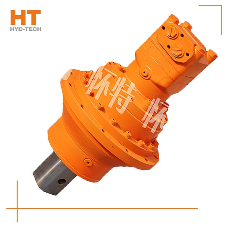
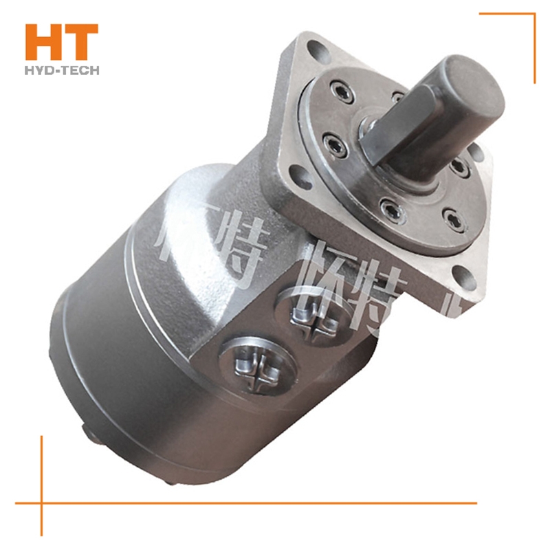
At present, the system used in series by multiple cycloidal motors (see Figure 1) is applied to sweepers, trenchless drills and airport luggage carts. The output shaft of the hydraulic motor often leaks oil during use, so it is useless to replace the dynamic seal of the output shaft. In series application, the problem of casing oil leakage pressure is ignored. The oil leakage pressure of the housing refers to the maximum pressure that the motor shaft seal can bear after the hydraulic motor is fully lubricated inside; If the hydraulic motor is applied customized Danfoss cycloid motor Improper. After the machine has been working continuously for a period of time, due to various factors, the oil in the housing will not be released, resulting in higher and higher pressure in the housing of the hydraulic motor, which first leads to the failure of the shaft seal. The casing leakage pressure mentioned here is not the bursting pressure of the casing, but the pressure that the motor output shaft dynamic seal can bear. In the motor samples of some manufacturers, only the back pressure is mentioned. Actually, back pressure refers to electricity Danfoss cycloid motor Manufacturer The return oil pressure of the engine, not the oil discharge pressure of the casing. During operation, the requirements for the oil discharge pressure of the cycloidal motor housing are as follows. Eaton is the world's first cycloid motor manufacturer. In China's domestic cycloidal motor manufacturing industry, Jining Jinjia Hydraulic Co., Ltd. uses Eaton technology to produce cycloidal motors. Its output shaft dynamic seal has better bearing capacity, that is, the unique internal oil circuit design of the company's products enables internal oil drainage not only to lubricate parts, but also to discharge excess oil while maintaining a certain housing oil drainage pressure.
Functions: It is used for the storage, supply and recovery of hydraulic media, the connection between hydraulic components and the transmission of energy carrying hydraulic media, filtering impurities in the hydraulic media, keeping the media required for the normal operation of the system clean, heating or cooling the system, storing and releasing hydraulic energy or absorbing hydraulic pulsation and impact, and displaying the pressure and oil temperature of the system; Hydraulic working medium: various hydraulic oils (fluids), efficacy: as the energy carrying medium of the system, it plays the role of lubrication and cooling while transferring energy. Generally speaking, the hydraulic components that can complete certain specific functions are called hydraulic circuits. In order to meet the working requirements of certain machinery or equipment, the overall structure of several special basic functional circuits connected or combined together is called hydraulic system.


