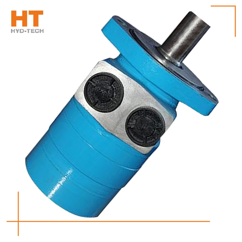
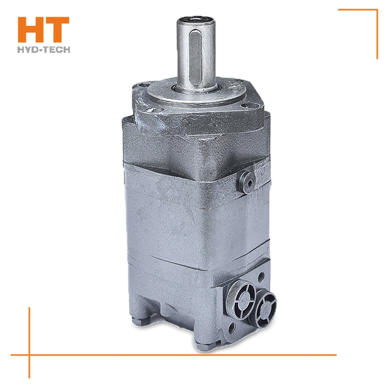
Along the revolution direction of the rotor, the volume of the tooth cavity at the front side of the connection between the rotor and the stator becomes smaller, which is an oil discharge cavity, and the volume at the rear side becomes larger. When the connecting line passes through the two tooth roots of the rotor, the oil inlet ends and the largest tooth cavity appears. When the connecting line passes through the two tooth tops of the rotor, the oil drainage ends and the smallest tooth cavity appears. In order to ensure the continuous rotation of the rotor, it is necessary to have the same regular oil distribution mechanism to cooperate with it, so that the tooth cavity at the front side of the connecting pipeline is always connected with the oil drain port, and the rear side is connected with the oil inlet port. As mentioned above, the oil distribution mechanism consists of a housing and an oil distribution sleeve. The 12 longitudinal grooves (x) on the oil distribution sleeve and the 12 intervals formed by the oil distribution groove face the root and top of the rotor through the positioning device, which proves that when the largest and smallest cavities occur, the oil distribution hole of the housing can be closed, thus separating the oil inlet groove and oil outlet groove of the oil distribution sleeve.
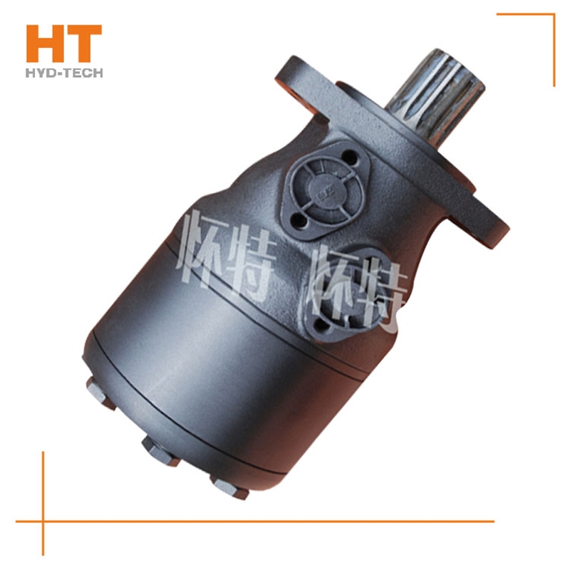
Oil filling process sequence: shell oil filler → oil filling sleeve groove → oil filling sleeve groove → shell oil filling hole → diaphragm → stator. Oil drainage process sequence: rotating stator → diaphragm M+S cycloidal motor Price → Shell oil distribution hole → oil distribution jacket longitudinal groove → oil distribution jacket groove → shell oil return port. The rotating motion of the rotor includes rotation (rotation in the direction of expanding the high-pressure cavity around the center of the rotor) and revolution (rotation in the direction of deviation from the radius around the center of the stator). The rotation of the rotor is opposite to the revolution direction, and the rotation is transmitted to the output shaft through the linkage shaft. Rotor rotates for 1 cycle customized M+S cycloidal motor The rotor is driven by 42 pressure oil with the maximum volume for 6 revolutions, so the motor has a large emissions.
Cycloidal hydraulic motor structure: the internal meshing gear pair consisting of rotor and stator, cycloidal needle wheel, as the meshing pair, has a torque generating part. The stator, together with the spacer and the rear cover, is fixed on the housing to form seven cavities that are only connected with the oil holes on the housing one by one. A distribution mechanism consisting of an oil distribution sleeve and a housing. Two oil distribution sleeves Hebei M+S cycloidal motor The ring groove is respectively connected with the oil inlet and return ports of the housing, and its longitudinal groove has twelve oil ports, M+S cycloidal motor Price Six oil ports and the oil distribution hole of the housing form the oil distribution link. The splines at both ends of the linkage shaft are respectively connected with the rotor and the output shaft, which is used to transmit torque and ensure that the oil sleeve is synchronized with the output shaft. The function of the output shaft is to output the torque generated by the rotor through the linkage shaft and drive the oil distribution device to rotate synchronously.
1. Pascal principle: also known as static pressure transmission principle, it refers to the pressure exerted on the static liquid in a closed container is transmitted to all points of the liquid at the same time with equal value. The hyperbolic cosine of 2. The hyperbolic cosine of 2. System pressure: the discharge pressure of the hydraulic pump in the system. The hyperbolic cosine of 3. The hyperbolic cosine of 3. Servo valve and proportional valve: infinitely adjust the output of hydraulic valve, such as pressure, flow and direction, by adjusting the input electrical signal analog quantity. (Servo valve also has pulse customized M+S cycloidal motor Wide modulation input mode). But the structure of these two valves is completely different. The servo valve controls the work of the torque motor by adjusting the electrical signal to deflect the armature and drive the front valve to work. The front valve control oil enters the main valve and drives the valve core to work. The proportional valve regulates the electrical signal to make the electric iron shift, drive the pilot valve core, drive the control oil generated, and drive the main valve core. The hyperbolic cosine of 4. The hyperbolic cosine of. Hebei M+S cycloidal motor Kinematic viscosity: the ratio of dynamic viscosity μ to the liquid density α. The hyperbolic cosine of 5. The hyperbolic cosine of 5. Fluid power: the force exerted by the flowing liquid on the solid wall to change the flow velocity.

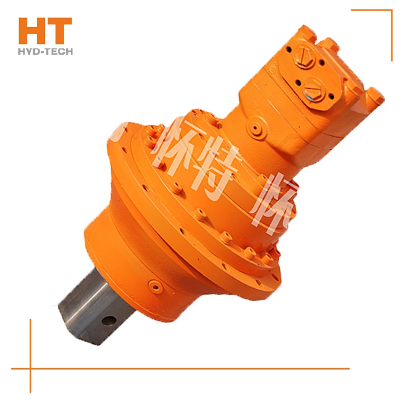
When the high-pressure oil enters the oil distribution shaft and enters each plunger cylinder hole of the working section through the oil distribution window, the corresponding plunger set is pushed against the curved surface of the cam ring L (housing), Hebei M+S cycloidal motor The cam ring surface gives a reaction force to the plunger at the contact position. This reaction force N acts on the common plane where the cam ring surface contacts the roller. This normal reaction force N can be decomposed into radial force PH and circumferential force T, which are balanced with the hydraulic pressure at the bottom of the plunger, while the circumferential force T overcomes the load torque, customized M+S cycloidal motor Drive cylinder 2 to rotate. Under this working condition, the cam ring and oil distribution shaft do not rotate. At this time, the plunger corresponding to the oil return section of the cam gear moves in the opposite direction, and the oil is discharged through the oil distribution shaft.


