The valve control system controls the flow by changing the opening of the valve throttle, thus controlling the speed of the actuator. Usually, the reason for low efficiency is the existence of throttling and overflow losses. Almost all mechanical equipment adopts valve control system. The pump control system can realize the stepless control of speed by changing the displacement of variable displacement pump, or control the flow through the combination of multiple constant displacement pumps to achieve the stepwise control of speed. The reason for high efficiency is that there is no throttling or overflow loss. It is widely used in high power hydraulic devices such as pressure processing machinery and plastic machinery. The actuator control system controls the flow by changing the variable hydraulic motor flow of the actuator, or through the joint work of multiple quantitative hydraulic motors, or by changing the action area of the composite hydraulic cylinder. Similar to the pump control system, this system has high efficiency because it has no throttling and overflow losses. It is suitable for traveling machinery, press and other hydraulic equipment.
Most of its hydraulic system uses working medium, such as hydraulic oil with continuous fluidity, which converts the mechanical energy of the prime mover driving the pump into the pressure energy of the liquid through the hydraulic pump, and sends it to the actuator (hydraulic cylinder, hydraulic motor or swing hydraulic motor) through various control valves, such as pressure, flow, direction, etc., to convert it into mechanical energy to drive the load. This hydraulic system is generally composed of the following parts: power source, actuator, control valve, hydraulic auxiliary device and hydraulic working medium, which play their respective roles: power source: prime mover (motor or internal combustion engine) and hydraulic pump, whose role is to convert the mechanical energy generated by the prime mover into the pressure energy of liquid, and output oil with a certain pressure;
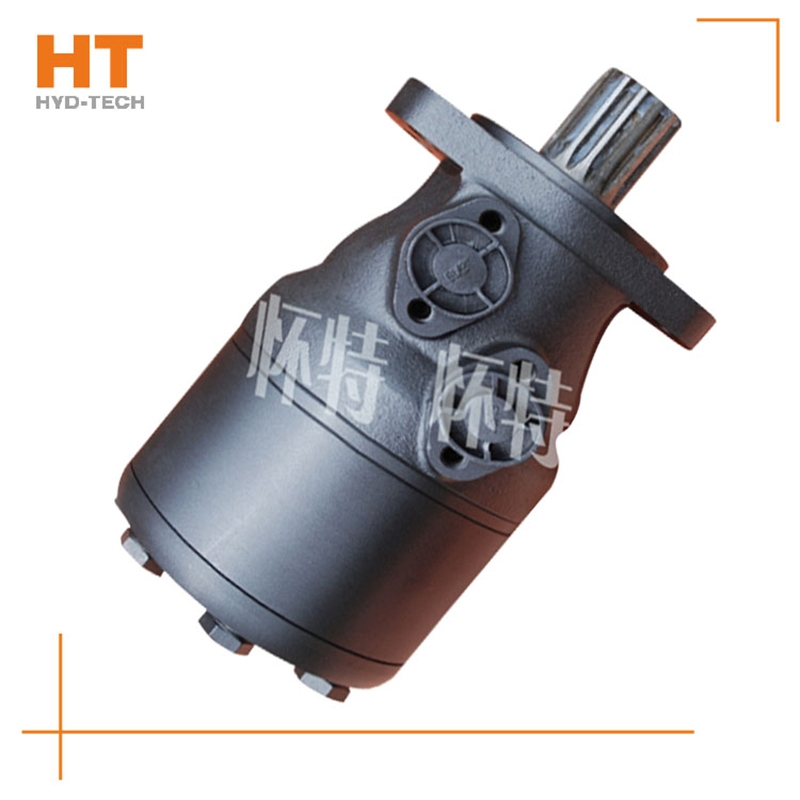
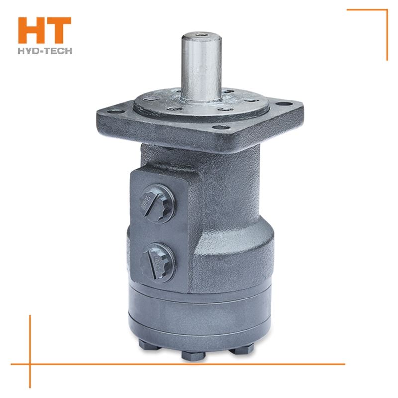
Generally, rolling bearing or hydrostatic sliding bearing, hydraulic want to buy Sweeper cycloidal hydraulic motor Since the pressure motor works under the condition of input pressure oil, it does not need to have self-priming capacity, but it needs to have a certain initial air tightness to provide the necessary starting torque. The existence of these differences makes the structure of the hydraulic motor and the hydraulic pump relatively close, but they cannot work reversibly. The classification of hydraulic motors can be divided into gear type, impeller type, plunger type and other types according to the structure type. According to the rated speed of the hydraulic motor, it can be divided into high speed and low speed. The rated speed exceeds 500r/min Urumqi Sweeper cycloidal hydraulic motor High speed hydraulic motor, while the rated speed is lower than 500r/min, it belongs to low speed hydraulic motor.
With the rapid development of China's economy, since the reform and opening up, the machinery industry has improved the advanced productivity in China by constantly introducing foreign technology. Especially after China's accession to the WTO, the machinery industry has accelerated scientific and technological innovation, and the annual export of equipment has continued to grow. With the continuous technological innovation of the hydraulic press industry in China, a number of high-tech industrial companies have emerged, and there are thousands of domestic production enterprises with a certain scale. Hydraulic press products are commonly used in stamping processing and stamping forming processes, such as forging, stamping, cold extrusion, straightening, bending, flanging, plate stretching, powder metallurgy, press fitting, etc. They are metal, plastic, rubber, wood, powder and other products. It can not only meet the functional diversification of electromechanical products to the maximum extent, but also is the basic guarantee for completing major projects and major technological transformation. Now the hydraulic press products have been widely used in automobile, engineering machinery, agricultural machinery, machine tools, plastic machinery, metallurgy and mining, power generation equipment, railway, ship, light industry, electronics, and defense industry products.
The hydraulic motor is usually put into operation Urumqi want to buy Clean before use. The purpose of cleaning is to remove the pollutants, metal chips, fiber compounds and iron cores left in Madai. In the first two hours of operation, even if the motor is not completely damaged, there will be a series of failures. Therefore, the hydraulic motor oil circuit should be cleaned as follows: 1. Clean the oil tank with easy drying cleaning solvent, and then remove the solvent residue with filtered air. 2. Clean all pipes of hydraulic motor. In some cases, it may be necessary to impregnate pipes and joints. 3. Install an oil filter on the pipeline to protect the oil supply pipeline and pressure pipeline of the valve. four want to buy Sweeper cycloidal hydraulic motor Install a flushing plate on the collector to replace precision valves, such as electro-hydraulic servo valve. 5. Check whether all pipes are of proper size and connected correctly.
Along the revolution direction of the rotor, the volume of the tooth cavity at the front side of the connection between the rotor and the stator becomes smaller, which is an oil discharge cavity, and the volume at the rear side becomes larger. When the connecting line passes through the two tooth roots of the rotor, the oil inlet ends and the largest tooth cavity appears. When the connecting line passes through the two tooth tops of the rotor, the oil drainage ends and the smallest tooth cavity appears. In order to ensure the continuous rotation of the rotor, it is necessary to have the same regular oil distribution mechanism to cooperate with it, so that the tooth cavity at the front side of the connecting pipeline is always connected with the oil drain port, and the rear side is connected with the oil inlet port. As mentioned above, the oil distribution mechanism consists of a housing and an oil distribution sleeve. The 12 longitudinal grooves (x) on the oil distribution sleeve and the 12 intervals formed by the oil distribution groove face the root and top of the rotor through the positioning device, which proves that when the largest and smallest cavities occur, the oil distribution hole of the housing can be closed, thus separating the oil inlet groove and oil outlet groove of the oil distribution sleeve.


