Functions: It is used for the storage, supply and recovery of hydraulic media, the connection between hydraulic components and the transmission of energy carrying hydraulic media, filtering impurities in the hydraulic media, keeping the media required for the normal operation of the system clean, heating or cooling the system, storing and releasing hydraulic energy or absorbing hydraulic pulsation and impact, and displaying the pressure and oil temperature of the system; Hydraulic working medium: various hydraulic oils (fluids), efficacy: as the energy carrying medium of the system, it plays the role of lubrication and cooling while transferring energy. Generally speaking, the hydraulic components that can complete certain specific functions are called hydraulic circuits. In order to meet the working requirements of certain machinery or equipment, the overall structure of several special basic functional circuits connected or combined together is called hydraulic system.
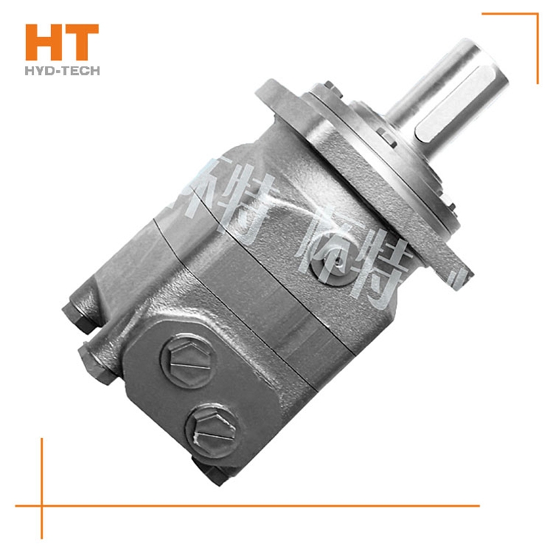
The output pressure of the hydraulic motor also depends on the load. Rated pressure Pn: the rated pressure refers to the working pressure that the hydraulic motor can withstand during continuous operation. It can customized Danfoss cycloid motor To ensure the volumetric efficiency and service life of the hydraulic motor. Working pressure P: the working pressure is the actual pressure of oil input when the hydraulic motor is working Danfoss cycloid motor Manufacturer power. Its value depends on the size of the load. However, the maximum working pressure is determined by the safety valve in the hydraulic system. The throttle adjustment value must not exceed the maximum pressure value of the hydraulic motor. The third is the maximum pressure: the limit pressure that the motor is allowed to overload in a short time. Pn ≤ Pmax value.
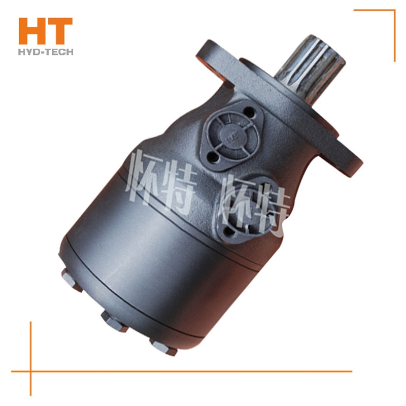
When the high-pressure oil enters the oil distribution shaft and enters each plunger cylinder hole of the working section through the oil distribution window, the corresponding plunger set is pushed against the curved surface of the cam ring L (housing), Shijiazhuang Danfoss cycloid motor The cam ring surface gives a reaction force to the plunger at the contact position. This reaction force N acts on the common plane where the cam ring surface contacts the roller. This normal reaction force N can be decomposed into radial force PH and circumferential force T, which are balanced with the hydraulic pressure at the bottom of the plunger, while the circumferential force T overcomes the load torque, customized Danfoss cycloid motor Drive cylinder 2 to rotate. Under this working condition, the cam ring and oil distribution shaft do not rotate. At this time, the plunger corresponding to the oil return section of the cam gear moves in the opposite direction, and the oil is discharged through the oil distribution shaft.
Of course, you can increase the traffic customized Danfoss cycloid motor Increase the speed, but how much will affect the service life. As long as it is within the rated power range, there is no problem. If the oil pressure reaches the rated pressure and the speed increases, it will exceed the power range it can withstand. Of course, it will damage the service life of the cycloidal hydraulic motor. Just like not eating so much hard food, it will damage the stomach. Increasing the flow can only increase the speed in a limited way, from 500 to 900, change the model of the motor, increase the flow of the cycloidal motor, increase the speed without control, increase the internal oil pressure, increase the internal leakage, directly reduce the efficiency, and damage the motor. Above Shijiazhuang Manufacturer Ming can try, and consult the cycloid hydraulic motor expert if he thinks the error is found.
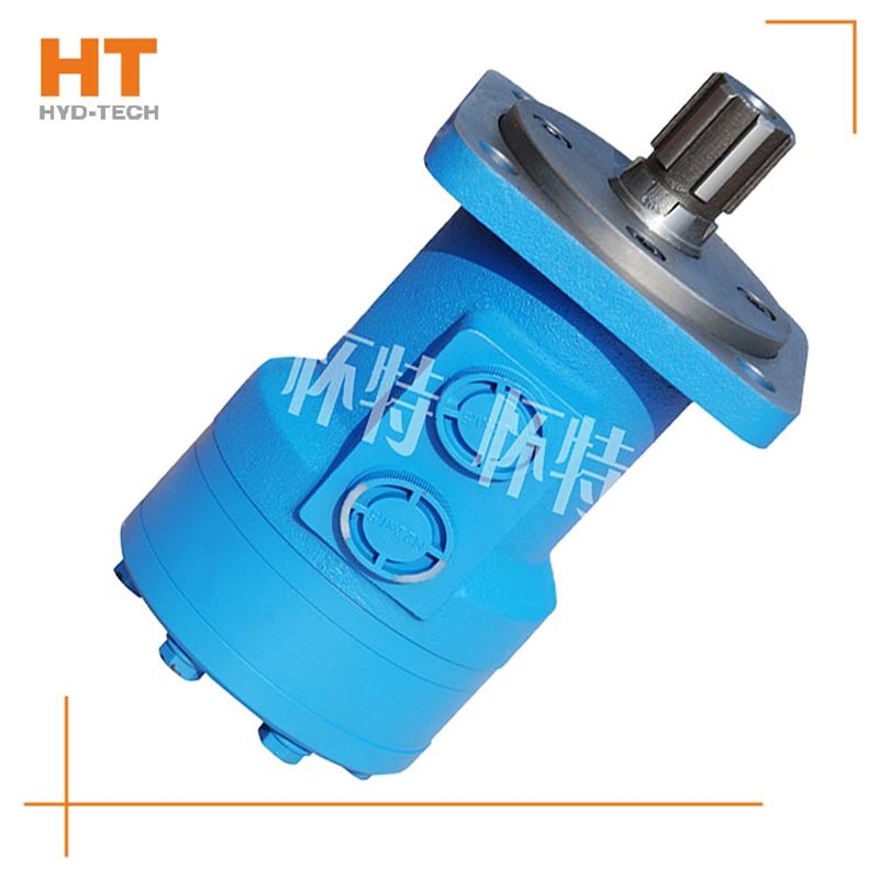
Along the revolution direction of the rotor, the volume of the tooth cavity at the front side of the connection between the rotor and the stator becomes smaller, which is an oil discharge cavity, and the volume at the rear side becomes larger. When the connecting line passes through the two tooth roots of the rotor, the oil inlet ends and the largest tooth cavity appears. When the connecting line passes through the two tooth tops of the rotor, the oil drainage ends and the smallest tooth cavity appears. In order to ensure the continuous rotation of the rotor, it is necessary to have the same regular oil distribution mechanism to cooperate with it, so that the tooth cavity at the front side of the connecting pipeline is always connected with the oil drain port, and the rear side is connected with the oil inlet port. As mentioned above, the oil distribution mechanism consists of a housing and an oil distribution sleeve. The 12 longitudinal grooves (x) on the oil distribution sleeve and the 12 intervals formed by the oil distribution groove face the root and top of the rotor through the positioning device, which proves that when the largest and smallest cavities occur, the oil distribution hole of the housing can be closed, thus separating the oil inlet groove and oil outlet groove of the oil distribution sleeve.