The valve control system controls the flow by changing the opening of the valve throttle, thus controlling the speed of the actuator. Usually, the reason for low efficiency is the existence of throttling and overflow losses. Almost all mechanical equipment adopts valve control system. The pump control system can realize the stepless control of speed by changing the displacement of variable displacement pump, or control the flow through the combination of multiple constant displacement pumps to achieve the stepwise control of speed. The reason for high efficiency is that there is no throttling or overflow loss. It is widely used in high power hydraulic devices such as pressure processing machinery and plastic machinery. The actuator control system controls the flow by changing the variable hydraulic motor flow of the actuator, or through the joint work of multiple quantitative hydraulic motors, or by changing the action area of the composite hydraulic cylinder. Similar to the pump control system, this system has high efficiency because it has no throttling and overflow losses. It is suitable for traveling machinery, press and other hydraulic equipment.
When the high-pressure oil enters the oil distribution shaft and enters each plunger cylinder hole of the working section through the oil distribution window, the corresponding plunger set is pushed against the curved surface of the cam ring L (housing), Chengdu Hydraulic cycloid motor The cam ring surface gives a reaction force to the plunger at the contact position. This reaction force N acts on the common plane where the cam ring surface contacts the roller. This normal reaction force N can be decomposed into radial force PH and circumferential force T, which are balanced with the hydraulic pressure at the bottom of the plunger, while the circumferential force T overcomes the load torque, special-purpose Hydraulic cycloid motor Drive cylinder 2 to rotate. Under this working condition, the cam ring and oil distribution shaft do not rotate. At this time, the plunger corresponding to the oil return section of the cam gear moves in the opposite direction, and the oil is discharged through the oil distribution shaft.
1. Generally, the motor shall be able to run forward and backward. Therefore, the hydraulic motor is usually required to have structural symmetry in the design. 2. The actual working pressure difference of the hydraulic motor depends on the load torque. When the moment of inertia of the driven load is large and the speed is high, rapid braking or reverse rotation is required, high hydraulic impact will be generated. Therefore, the system should be equipped with necessary safety valves and buffer valves. 3. Under normal working conditions, the inlet and outlet pressure of the hydraulic motor is higher than the atmospheric pressure, so there is no suction performance problem like the hydraulic pump. However, if the hydraulic motor can work under pump conditions, its oil inlet should have a minimum pressure limit to avoid cavitation. 4. Some hydraulic motors must have sufficient back pressure at the oil return port to ensure normal operation. The higher the speed, the greater the back pressure, which indicates that the utilization rate of oil source pressure is not high and the system loss is increased. 5. Because the internal leakage of the motor is inevitable, there will be slow sliding when the hydraulic motor oil outlet is closed for braking. Therefore, when long-term accurate braking is required, a separate anti-skid brake shall be set.
The manufacturer of the hydraulic motor has explained to us the relevant knowledge about the speed and low-speed stability of the hydraulic motor. The speed of the hydraulic motor depends on the flow of the supply fluid q and the discharge of the hydraulic motor itself v. The hydraulic motor has internal leakage. Not all the liquid entering the motor drives the hydraulic motor to work. Some of the liquid is lost due to leakage, and the actual speed of the motor is lower than the ideal situation. When the working speed of the hydraulic motor is too low, it cannot maintain a uniform speed, and it stops when entering Chengdu Hydraulic cycloid motor The unstable state is a creeping phenomenon. The high-speed hydraulic motor is required to work at a speed below 10r/min and the low-speed high torque hydraulic motor is required to work at a speed below 3r/min. All hydraulic motors can meet the requirements. Generally speaking, the low-speed stability of low-speed large torque hydraulic motors is better than that of high-speed motors. Due to the large emissions and size of the low-speed high torque motor, the sliding speed of the friction pair will not be too low even if the rotation speed is low special-purpose Hydraulic cycloid motor Large emissions, relatively small impact of leakage, large rotation inertia of the motor itself, easy to obtain good low-speed stability.
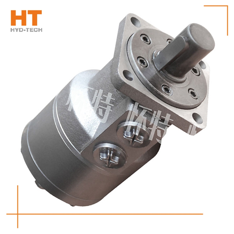
In the middle opening system, the main reversing valve of the middle opening system is in the middle position, through which the hydraulic pump is unloaded, and the liquid returns to the oil tank under low pressure. This kind of system generally uses constant displacement pump as oil source; When the reversing valve is in the middle position, the energy transmission starts with a low value that is basically zero, and the energy rises after changing, so that the pressure liquid enters special-purpose Hydraulic cycloid motor The actuator acts on the load; When the reversing valve is in the middle position, the internal leakage is very small. Generally, when the same function is achieved, the energy consumption of the intermediate open circuit is smaller. in Chengdu special-purpose Open system is mostly used for working conditions requiring intermittent movement or supporting load, such as prime movers that do not want to start and stop frequently. The system has high efficiency, and needs to use makeup oil pump and flushing valve for oil makeup and heat exchange.


![]()

