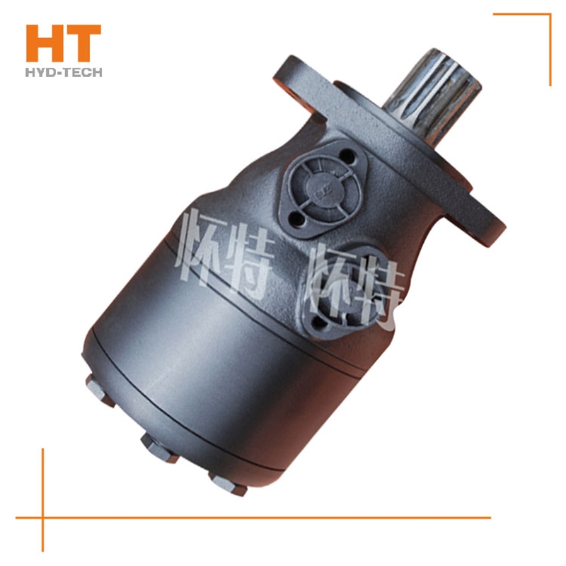
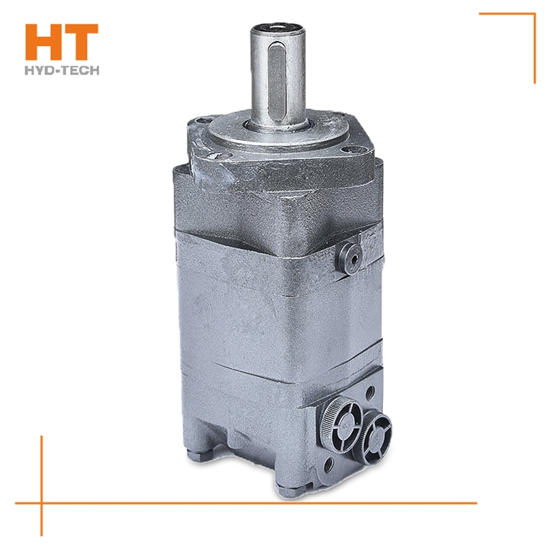
BM cycloidal hydraulic motor is a small low-speed high torque hydraulic motor with single axis flow distribution and fixed rotor set. Its advantages are as follows: 1. It is small in size and light in weight, and its overall size is much smaller than other types of hydraulic motors with the same torque. 2. Wide speed range, stepless speed regulation, minimum stable speed up to 15 rpm, convenient installation and layout, low investment cost. 3. It can be used in series or parallel in the hydraulic system. 4. The moment of inertia is small, and it is easy to start under load. It can rotate in both forward and reverse directions, and it does not need to stop when reversing. BM cycloidal motor is widely used in agriculture, fishery, light industry Cycloidal hydraulic motor brake Manufacturer The slewing mechanism of hoisting and transportation, mining, construction machinery and other machinery. Examples of BM cycloidal hydraulic motor used abroad; 1) Agricultural use: various combine harvesters, seeders, rotary tillers, lawn mowers, sprayers, feed mixers, ground drills. 2) Fishery use: net lifter. want to buy Cycloidal hydraulic motor brake 3) Light industry: commercial winding machines, textile machines, printing machines, washing machines. 4) For construction industry: road roller, cement mixer, sweeper.
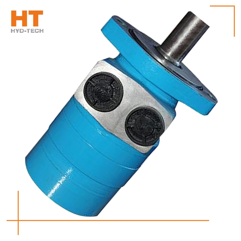
Cycloidal hydraulic motor, as a kind of construction machinery equipment with small price increase and light weight, is also widely used in daily life. Cycloidal hydraulic motor is a kind of motor, which is essential for some equipment. In fact, the operation of all hydraulic systems is almost the same. This cycloidal hydraulic motor is widely used Nanning want to buy It is used in construction, manufacturing, mining and other industries, so pay attention to daily maintenance when using the motor to ensure the service life of the cycloidal hydraulic motor. In order to keep the whole system in a stable state, it is necessary to ensure that the motor function has a constant pressure, ensure that the hydraulic system is normal, and ensure that the pressure in the system is not Cycloidal hydraulic motor brake Manufacturer leak.
Causes: 1. The pump is damaged, and the pump body is overheated and produces noise. 2. The control valve is closed tightly or the oil supply and return system is blocked, and local overheating occurs. 3. The safety valve is opened, and the valve cries or hisses, and local overheating occurs. 4. The distribution rotary valve is excessively leaking, and the valve chamber is overheated, and it is very hot when touched by hand. 5. The hydraulic motor crankcase is excessively leaking, and the single oil drain pipe is leaking want to buy Cycloidal hydraulic motor brake Treatment method for excessive leakage and high oil level: 1. Check the condition of the ball joint 2. Check the sealing condition of the cylinder piston 3. Check the viscosity and operating temperature of the oil 4. Check the contact surface between the oil pan and the housing 5. Check the surface between the connecting rod and the eccentric wheel Cycloidal hydraulic motor brake Manufacturer 6. Check the wear of the oil pan and whether the two oil cavity channels at the inlet and outlet of the casting are connected
System for fixed equipment. This hydraulic system is mostly an open cycle system, including machine tools (workpiece clamping, worktable feeding, direction exchange, spindle drive), presses (pressing, blank holder, direction exchange, workpiece ejection), die-casting machines and injection molding machines (mold closing, demoulding, preforming, injection mechanisms), medical devices, garbage compression and other mechanical devices Nanning want to buy System of standby and working devices. The hydraulic system for traveling equipment includes both open circulation system and closed circulation system, including vehicle driving (traveling drive, steering, braking and working equipment Cycloidal hydraulic motor brake Manufacturer ), material conveying, loading, unloading and conveying equipment (conveying mechanism, transposition mechanism), various systems of aviation, space and navigation engineering.
Most of its hydraulic system uses working medium, such as hydraulic oil with continuous fluidity, which converts the mechanical energy of the prime mover driving the pump into the pressure energy of the liquid through the hydraulic pump, and sends it to the actuator (hydraulic cylinder, hydraulic motor or swing hydraulic motor) through various control valves, such as pressure, flow, direction, etc., to convert it into mechanical energy to drive the load. This hydraulic system is generally composed of the following parts: power source, actuator, control valve, hydraulic auxiliary device and hydraulic working medium, which play their respective roles: power source: prime mover (motor or internal combustion engine) and hydraulic pump, whose role is to convert the mechanical energy generated by the prime mover into the pressure energy of liquid, and output oil with a certain pressure;
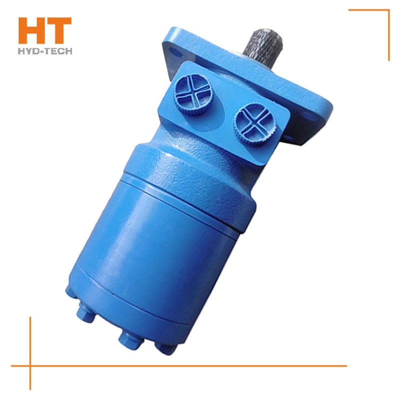
Along the revolution direction of the rotor, the volume of the tooth cavity at the front side of the connection between the rotor and the stator becomes smaller, which is an oil discharge cavity, and the volume at the rear side becomes larger. When the connecting line passes through the two tooth roots of the rotor, the oil inlet ends and the largest tooth cavity appears. When the connecting line passes through the two tooth tops of the rotor, the oil drainage ends and the smallest tooth cavity appears. In order to ensure the continuous rotation of the rotor, it is necessary to have the same regular oil distribution mechanism to cooperate with it, so that the tooth cavity at the front side of the connecting pipeline is always connected with the oil drain port, and the rear side is connected with the oil inlet port. As mentioned above, the oil distribution mechanism consists of a housing and an oil distribution sleeve. The 12 longitudinal grooves (x) on the oil distribution sleeve and the 12 intervals formed by the oil distribution groove face the root and top of the rotor through the positioning device, which proves that when the largest and smallest cavities occur, the oil distribution hole of the housing can be closed, thus separating the oil inlet groove and oil outlet groove of the oil distribution sleeve.


![]()

