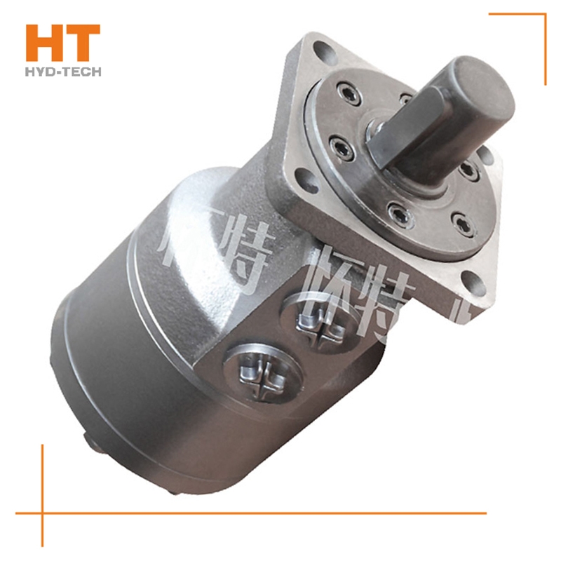
Causes: 1. The pump is damaged, and the pump body is overheated and produces noise. 2. The control valve is closed tightly or the oil supply and return system is blocked, and local overheating occurs. 3. The safety valve is opened, and the valve cries or hisses, and local overheating occurs. 4. The distribution rotary valve is excessively leaking, and the valve chamber is overheated, and it is very hot when touched by hand. 5. The hydraulic motor crankcase is excessively leaking, and the single oil drain pipe is leaking special-purpose M+S cycloidal motor Treatment method for excessive leakage and high oil level: 1. Check the condition of the ball joint 2. Check the sealing condition of the cylinder piston 3. Check the viscosity and operating temperature of the oil 4. Check the contact surface between the oil pan and the housing 5. Check the surface between the connecting rod and the eccentric wheel M+S cycloidal motor Manufacturer 6. Check the wear of the oil pan and whether the two oil cavity channels at the inlet and outlet of the casting are connected
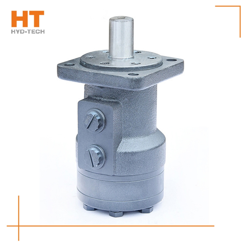
Most of its hydraulic system uses working medium, such as hydraulic oil with continuous fluidity, which converts the mechanical energy of the prime mover driving the pump into the pressure energy of the liquid through the hydraulic pump, and sends it to the actuator (hydraulic cylinder, hydraulic motor or swing hydraulic motor) through various control valves, such as pressure, flow, direction, etc., to convert it into mechanical energy to drive the load. This hydraulic system is generally composed of the following parts: power source, actuator, control valve, hydraulic auxiliary device and hydraulic working medium, which play their respective roles: power source: prime mover (motor or internal combustion engine) and hydraulic pump, whose role is to convert the mechanical energy generated by the prime mover into the pressure energy of liquid, and output oil with a certain pressure;
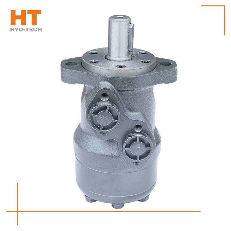
As a kind of hydraulic transmission device, hydraulic motor has been widely used in many places. In fact, I have seen it on many occasions. The main application fields are. 1. The hydraulic motor has convenient speed regulation, which can be adjusted infinitely from 0 to the maximum speed according to the adjustment of the hydraulic valve. The motor itself does not need special design and has low cost. This is much cheaper than motor+reducer, or variable frequency motor and servo motor. 2. The hydraulic system has strong anti overload capacity and relies on the overflow valve for protection, allowing a long time special-purpose M+S cycloidal motor (Relatively) Frequent overload, easy to recover under overload, no damage to equipment, no restart of equipment. 3. The hydraulic system is characterized by high energy density. For motors of the same power, hydraulic motors are much smaller than motors M+S cycloidal motor Manufacturer , much lighter. And it is easy to apply to mobile devices. 4. The hydraulic motor is totally enclosed and can be safely used in dusty, wet (even underwater) and flammable environments, which is much more reliable than explosion-proof (flameproof) motors.
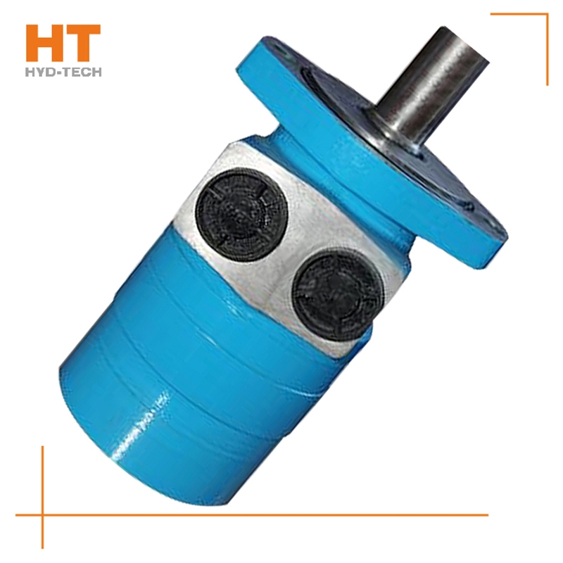
1) Select the hydraulic pump or motor with good quality and conduct regular maintenance. For example, if the tooth profile accuracy of the gear is low, grind the gear to meet the requirements of the contact surface; 2) If the vane pump has trapped oil, the triangular groove of the oil distributor should be corrected to remove the trapped oil; 3) If the axial clearance of the hydraulic pump is too large and the oil delivery is insufficient M+S cycloidal motor Manufacturer Repair to keep the axial clearance within the allowable range; 4) If the hydraulic pump is not selected correctly, it should be replaced immediately. 3. The reversing valve is improperly adjusted. Improper adjustment of the reversing valve causes the valve core of the reversing valve to move too fast, resulting in reversing shock, noise and vibration. During operation, the valve core branch of hydraulic valve Puyang M+S cycloidal motor Support on the spring. When its frequency is close to the pulsating frequency of oil delivery rate of hydraulic pump or other vibration sources, vibration and noise will be generated.
The ignition time of internal combustion engines can be compared with this. It can be seen from the working principle of the cycloidal hydraulic motor that the oil sleeve and the rotor rotate synchronously, and the accuracy refers to the accuracy of the oil distribution link matching with the rotor to rotate the oil inlet, seal and discharge. There are many factors special-purpose M+S cycloidal motor It will affect the oil distribution accuracy, such as the asymmetry of the rotor spline and cycloid tooth shape, the relative position accuracy of the stator sleeve needle hole and bolt hole, and the relative position asymmetry of the pin hole and spline on the output shaft and its internal spline, M+S cycloidal motor Manufacturer The relative position accuracy of the longitudinal oil groove and the relative wedge groove of the coupling, and the asymmetry of splines at both ends of the coupling. As long as the above factors are controlled within the tolerance range, they will not have a great impact on the oil distribution accuracy, because all processing errors will not be offset.
Along the revolution direction of the rotor, the volume of the tooth cavity at the front side of the connection between the rotor and the stator becomes smaller, which is an oil discharge cavity, and the volume at the rear side becomes larger. When the connecting line passes through the two tooth roots of the rotor, the oil inlet ends and the largest tooth cavity appears. When the connecting line passes through the two tooth tops of the rotor, the oil drainage ends and the smallest tooth cavity appears. In order to ensure the continuous rotation of the rotor, it is necessary to have the same regular oil distribution mechanism to cooperate with it, so that the tooth cavity at the front side of the connecting pipeline is always connected with the oil drain port, and the rear side is connected with the oil inlet port. As mentioned above, the oil distribution mechanism consists of a housing and an oil distribution sleeve. The 12 longitudinal grooves (x) on the oil distribution sleeve and the 12 intervals formed by the oil distribution groove face the root and top of the rotor through the positioning device, which proves that when the largest and smallest cavities occur, the oil distribution hole of the housing can be closed, thus separating the oil inlet groove and oil outlet groove of the oil distribution sleeve.


![]()

