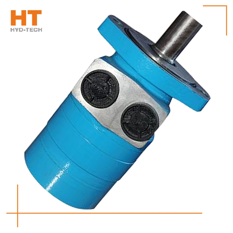
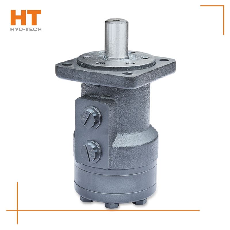
At present, the system used in series by multiple cycloidal motors (see Figure 1) is applied to sweepers, trenchless drills and airport luggage carts. The output shaft of the hydraulic motor often leaks oil during use, so it is useless to replace the dynamic seal of the output shaft. In series application, the problem of casing oil leakage pressure is ignored. The oil leakage pressure of the housing refers to the maximum pressure that the motor shaft seal can bear after the hydraulic motor is fully lubricated inside; If the hydraulic motor is applied special-purpose Cycloid hydraulic motor Improper. After the machine has been working continuously for a period of time, due to various factors, the oil in the housing will not be released, resulting in higher and higher pressure in the housing of the hydraulic motor, which first leads to the failure of the shaft seal. The casing leakage pressure mentioned here is not the bursting pressure of the casing, but the pressure that the motor output shaft dynamic seal can bear. In the motor samples of some manufacturers, only the back pressure is mentioned. Actually, back pressure refers to electricity Cycloid hydraulic motor Manufacturer The return oil pressure of the engine, not the oil discharge pressure of the casing. During operation, the requirements for the oil discharge pressure of the cycloidal motor housing are as follows. Eaton is the world's first cycloid motor manufacturer. In China's domestic cycloidal motor manufacturing industry, Jining Jinjia Hydraulic Co., Ltd. uses Eaton technology to produce cycloidal motors. Its output shaft dynamic seal has better bearing capacity, that is, the unique internal oil circuit design of the company's products enables internal oil drainage not only to lubricate parts, but also to discharge excess oil while maintaining a certain housing oil drainage pressure.
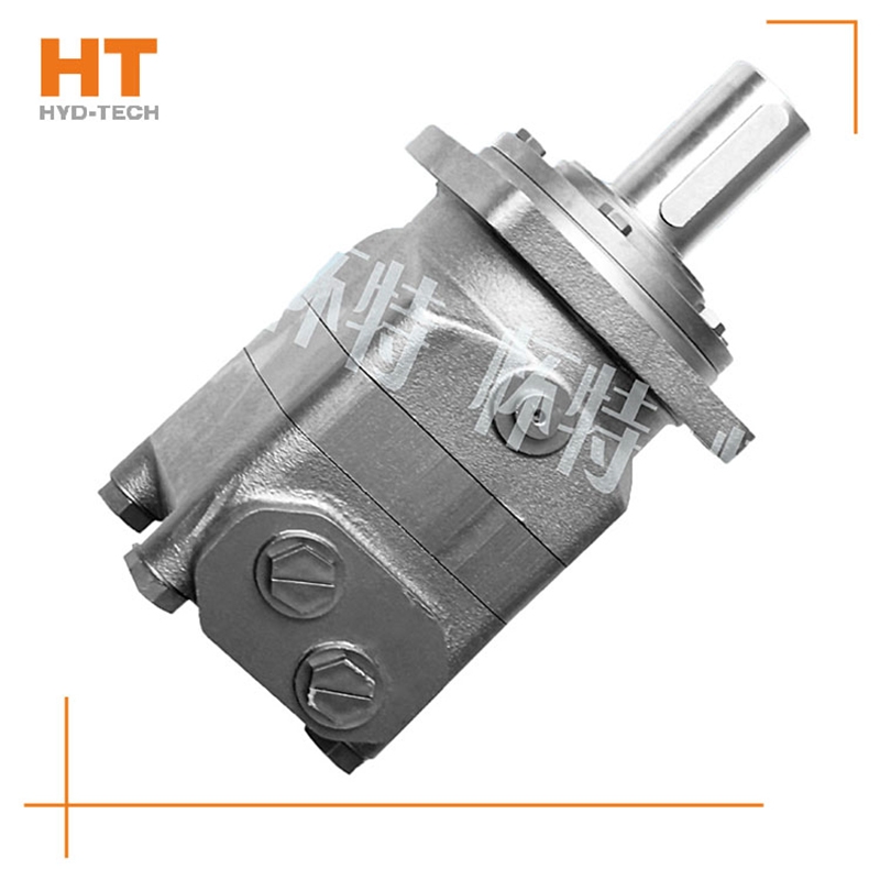
Oil filling process sequence: shell oil filler → oil filling sleeve groove → oil filling sleeve groove → shell oil filling hole → diaphragm → stator. Oil drainage process sequence: rotating stator → diaphragm Cycloid hydraulic motor Manufacturer → Shell oil distribution hole → oil distribution jacket longitudinal groove → oil distribution jacket groove → shell oil return port. The rotating motion of the rotor includes rotation (rotation in the direction of expanding the high-pressure cavity around the center of the rotor) and revolution (rotation in the direction of deviation from the radius around the center of the stator). The rotation of the rotor is opposite to the revolution direction, and the rotation is transmitted to the output shaft through the linkage shaft. Rotor rotates for 1 cycle special-purpose Cycloid hydraulic motor The rotor is driven by 42 pressure oil with the maximum volume for 6 revolutions, so the motor has a large emissions.
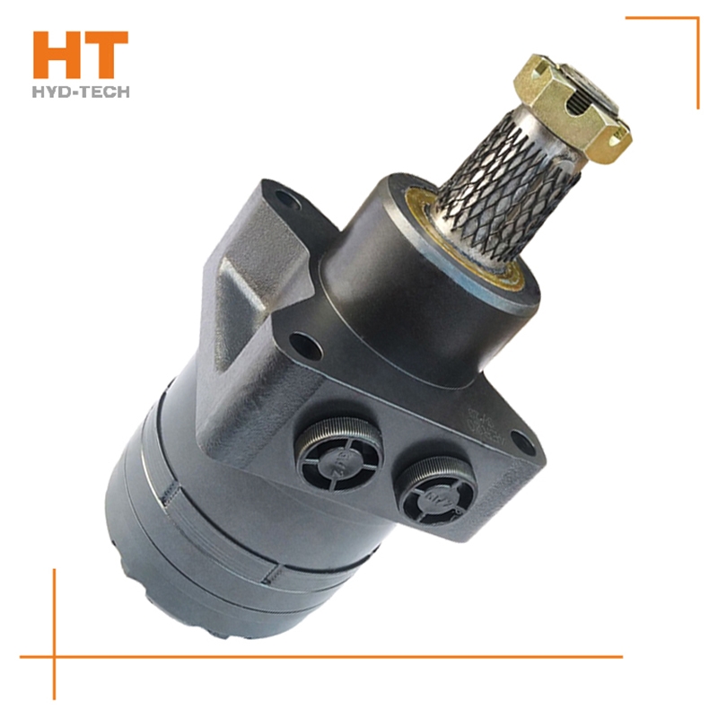
The valve control system controls the flow by changing the opening of the valve throttle, thus controlling the speed of the actuator. Usually, the reason for low efficiency is the existence of throttling and overflow losses. Almost all mechanical equipment adopts valve control system. The pump control system can realize the stepless control of speed by changing the displacement of variable displacement pump, or control the flow through the combination of multiple constant displacement pumps to achieve the stepwise control of speed. The reason for high efficiency is that there is no throttling or overflow loss. It is widely used in high power hydraulic devices such as pressure processing machinery and plastic machinery. The actuator control system controls the flow by changing the variable hydraulic motor flow of the actuator, or through the joint work of multiple quantitative hydraulic motors, or by changing the action area of the composite hydraulic cylinder. Similar to the pump control system, this system has high efficiency because it has no throttling and overflow losses. It is suitable for traveling machinery, press and other hydraulic equipment.
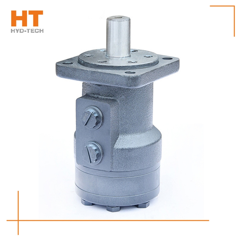
As far as energy conversion is concerned, the hydraulic pump and hydraulic motor are connected as reversible hydraulic components, and the working fluid can be input into any kind of hydraulic pump to make it become a hydraulic motor; On the contrary, when the main shaft of the hydraulic motor rotates under the action of external force Cycloid hydraulic motor Manufacturer It can also become a hydraulic pump. Because they all have the same basic structural elements, namely sealed and recyclable volume and corresponding distribution mechanism. However, the working environment of hydraulic motor and hydraulic pump is different special-purpose Cycloid hydraulic motor The performance requirements are also different. Therefore, there are many differences between the hydraulic motor and the hydraulic pump of the same model. The first hydraulic motor should be positive and negative, so its internal structure should be symmetrical; The speed range of the motor must be large enough, especially its minimum stable speed must have certain requirements.
The hydraulic motor has two circuits: the hydraulic motor series circuit and the hydraulic motor braking circuit. These two circuits can be classified into the next category. One of the series circuits of hydraulic motors: three hydraulic motors are connected in series with each other, and a reversing valve is used to control the start stop and steering. The flow through the three motors is basically the same. When the displacement is the same, the speed of each motor is basically the same. The oil supply pressure of the hydraulic pump Jilin Manufacturer High, small pump flow, generally used for light load and high speed. Serial circuit II of hydraulic motor: each reversing valve in this circuit controls one motor, each motor can work independently or simultaneously, and the rotation direction of each motor is also special-purpose Cycloid hydraulic motor optional. The oil supply pressure of the hydraulic pump is the sum of the working pressure difference of each motor, which is applicable to the condition of high speed and small torque.


![]()

