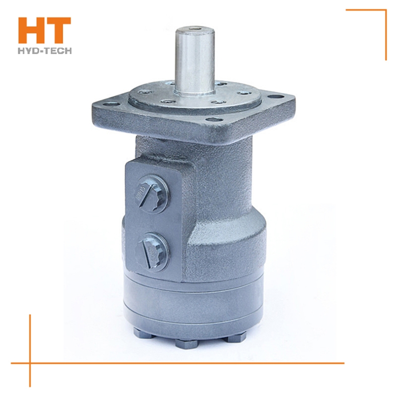
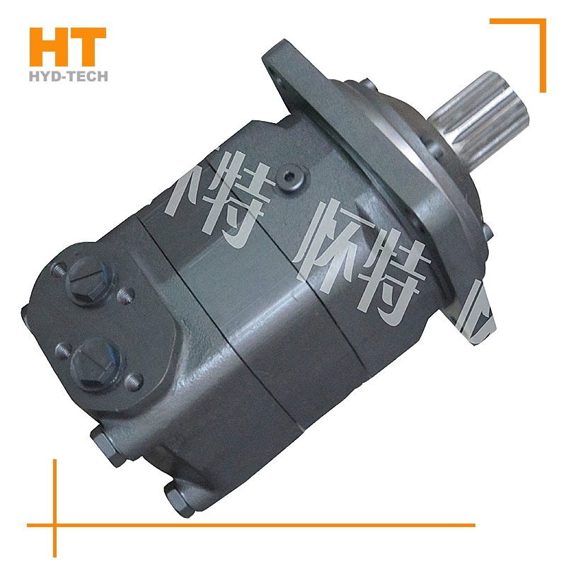
After disassembling and inspecting the hydraulic motor installed on the drill, it was found that the friction surface of the valve disc and the port plate of the hydraulic motor was severely worn, and the deepest worn part was 0. 15mm; The output shaft oil seal is leaking. Cause analysis of oil leakage of output shaft oil seal. After disassembly inspection and test, the axial and radial clearances of the output shaft meet the standard requirements want to buy Large torque cycloidal motor There is no obvious wear on the oil seal mating surface. However, it is found that the oil seal rubber has hardened and its elasticity has deteriorated. With the increase of sealing lip wear, the pre tightening capacity and sealing performance decrease, and the excessive oil temperature accelerates the wear of sealing lip; In addition, due to the liquid Shenzhen Large torque cycloidal motor The leakage of the pressure motor causes the back pressure in the housing to be too high, which further aggravates the wear and leakage of the sealing lip. The smaller the friction of the rotor in the stator sleeve, the higher the mechanical efficiency of the motor.
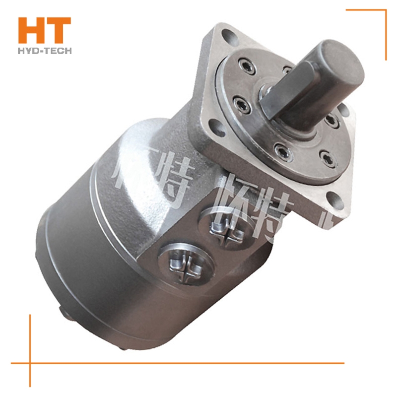
At present, the system used in series by multiple cycloidal motors (see Figure 1) is applied to sweepers, trenchless drills and airport luggage carts. The output shaft of the hydraulic motor often leaks oil during use, so it is useless to replace the dynamic seal of the output shaft. In series application, the problem of casing oil leakage pressure is ignored. The oil leakage pressure of the housing refers to the maximum pressure that the motor shaft seal can bear after the hydraulic motor is fully lubricated inside; If the hydraulic motor is applied want to buy Large torque cycloidal motor Improper. After the machine has been working continuously for a period of time, due to various factors, the oil in the housing will not be released, resulting in higher and higher pressure in the housing of the hydraulic motor, which first leads to the failure of the shaft seal. The casing leakage pressure mentioned here is not the bursting pressure of the casing, but the pressure that the motor output shaft dynamic seal can bear. In the motor samples of some manufacturers, only the back pressure is mentioned. Actually, back pressure refers to electricity Large torque cycloidal motor Manufacturer The return oil pressure of the engine, not the oil discharge pressure of the casing. During operation, the requirements for the oil discharge pressure of the cycloidal motor housing are as follows. Eaton is the world's first cycloid motor manufacturer. In China's domestic cycloidal motor manufacturing industry, Jining Jinjia Hydraulic Co., Ltd. uses Eaton technology to produce cycloidal motors. Its output shaft dynamic seal has better bearing capacity, that is, the unique internal oil circuit design of the company's products enables internal oil drainage not only to lubricate parts, but also to discharge excess oil while maintaining a certain housing oil drainage pressure.
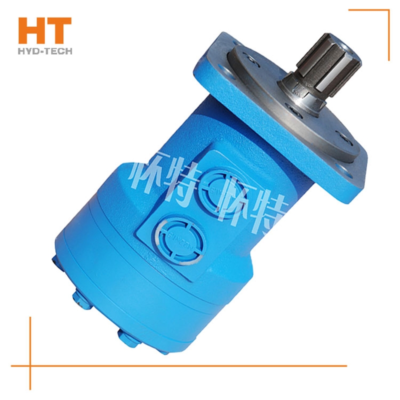
The manufacturer of the hydraulic motor has explained to us the relevant knowledge about the speed and low-speed stability of the hydraulic motor. The speed of the hydraulic motor depends on the flow of the supply fluid q and the discharge of the hydraulic motor itself v. The hydraulic motor has internal leakage. Not all the liquid entering the motor drives the hydraulic motor to work. Some of the liquid is lost due to leakage, and the actual speed of the motor is lower than the ideal situation. When the working speed of the hydraulic motor is too low, it cannot maintain a uniform speed, and it stops when entering Shenzhen Large torque cycloidal motor The unstable state is a creeping phenomenon. The high-speed hydraulic motor is required to work at a speed below 10r/min and the low-speed high torque hydraulic motor is required to work at a speed below 3r/min. All hydraulic motors can meet the requirements. Generally speaking, the low-speed stability of low-speed large torque hydraulic motors is better than that of high-speed motors. Due to the large emissions and size of the low-speed high torque motor, the sliding speed of the friction pair will not be too low even if the rotation speed is low want to buy Large torque cycloidal motor Large emissions, relatively small impact of leakage, large rotation inertia of the motor itself, easy to obtain good low-speed stability.
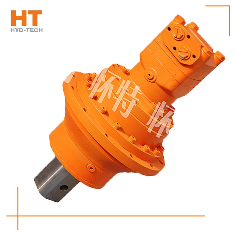
Along the revolution direction of the rotor, the volume of the tooth cavity at the front side of the connection between the rotor and the stator becomes smaller, which is an oil discharge cavity, and the volume at the rear side becomes larger. When the connecting line passes through the two tooth roots of the rotor, the oil inlet ends and the largest tooth cavity appears. When the connecting line passes through the two tooth tops of the rotor, the oil drainage ends and the smallest tooth cavity appears. In order to ensure the continuous rotation of the rotor, it is necessary to have the same regular oil distribution mechanism to cooperate with it, so that the tooth cavity at the front side of the connecting pipeline is always connected with the oil drain port, and the rear side is connected with the oil inlet port. As mentioned above, the oil distribution mechanism consists of a housing and an oil distribution sleeve. The 12 longitudinal grooves (x) on the oil distribution sleeve and the 12 intervals formed by the oil distribution groove face the root and top of the rotor through the positioning device, which proves that when the largest and smallest cavities occur, the oil distribution hole of the housing can be closed, thus separating the oil inlet groove and oil outlet groove of the oil distribution sleeve.
The valve control system controls the flow by changing the opening of the valve throttle, thus controlling the speed of the actuator. Usually, the reason for low efficiency is the existence of throttling and overflow losses. Almost all mechanical equipment adopts valve control system. The pump control system can realize the stepless control of speed by changing the displacement of variable displacement pump, or control the flow through the combination of multiple constant displacement pumps to achieve the stepwise control of speed. The reason for high efficiency is that there is no throttling or overflow loss. It is widely used in high power hydraulic devices such as pressure processing machinery and plastic machinery. The actuator control system controls the flow by changing the variable hydraulic motor flow of the actuator, or through the joint work of multiple quantitative hydraulic motors, or by changing the action area of the composite hydraulic cylinder. Similar to the pump control system, this system has high efficiency because it has no throttling and overflow losses. It is suitable for traveling machinery, press and other hydraulic equipment.


![]()

