The output pressure of the hydraulic motor also depends on the load. Rated pressure Pn: the rated pressure refers to the working pressure that the hydraulic motor can withstand during continuous operation. It can special-purpose Cycloid hydraulic motor To ensure the volumetric efficiency and service life of the hydraulic motor. Working pressure P: the working pressure is the actual pressure of oil input when the hydraulic motor is working Cycloid hydraulic motor Manufacturer power. Its value depends on the size of the load. However, the maximum working pressure is determined by the safety valve in the hydraulic system. The throttle adjustment value must not exceed the maximum pressure value of the hydraulic motor. The third is the maximum pressure: the limit pressure that the motor is allowed to overload in a short time. Pn ≤ Pmax value.
As the power source and actuator of the hydraulic system, the performance of the hydraulic motor has a great impact on the performance of the entire hydraulic system. Therefore, the importance of studying the hydraulic motor performance test system is special-purpose Cycloid hydraulic motor It is very important that the rise and application of hydraulic testing technology based on virtual instrument has opened up a broad prospect for the performance testing of hydraulic motors. Hydraulic motors are widely used in machine tools, metallurgy, engineering machinery, plastic machinery, agricultural machinery, mining machinery, marine machinery and many other important fields. The performance of the hydraulic motor has a decisive impact on the whole system, and will directly affect the stability of the system. At the same time, the performance of the hydraulic motor will have an impact on the life of the system components and the production efficiency of the system. ynz Manufacturer Unexpected failure of hydraulic motor will greatly reduce production efficiency.
1. Pascal principle: also known as static pressure transmission principle, it refers to the pressure exerted on the static liquid in a closed container is transmitted to all points of the liquid at the same time with equal value. The hyperbolic cosine of 2. The hyperbolic cosine of 2. System pressure: the discharge pressure of the hydraulic pump in the system. The hyperbolic cosine of 3. The hyperbolic cosine of 3. Servo valve and proportional valve: infinitely adjust the output of hydraulic valve, such as pressure, flow and direction, by adjusting the input electrical signal analog quantity. (Servo valve also has pulse special-purpose Cycloid hydraulic motor Wide modulation input mode). But the structure of these two valves is completely different. The servo valve controls the work of the torque motor by adjusting the electrical signal to deflect the armature and drive the front valve to work. The front valve control oil enters the main valve and drives the valve core to work. The proportional valve regulates the electrical signal to make the electric iron shift, drive the pilot valve core, drive the control oil generated, and drive the main valve core. The hyperbolic cosine of 4. The hyperbolic cosine of. ynz Cycloid hydraulic motor Kinematic viscosity: the ratio of dynamic viscosity μ to the liquid density α. The hyperbolic cosine of 5. The hyperbolic cosine of 5. Fluid power: the force exerted by the flowing liquid on the solid wall to change the flow velocity.
As a hydraulic equipment, hydraulic motor has been widely used in many factories. Generally, we should master the assembly skills of the hydraulic motor: the hydraulic system should special-purpose Cycloid hydraulic motor Correct machining and assembly. The mounting surface of the hydraulic valve on the oil block should be straight, and the sealing surface of the sealing groove should be finished to avoid radial scratches. The preload of the connection between the hydraulic valve and the oil circuit block and the connection between the oil circuit blocks shall be sufficient to prevent surface separation. The hydraulic equipment shall be inspected according to relevant standards before assembly Cycloid hydraulic motor Manufacturer Check the pressure leakage of system components. If problems are found, corresponding measures shall be taken. If the problem is serious, it should be replaced. Accurately formulate the assembly process documents of hydraulic equipment, configure necessary assembly tools, and strictly follow the assembly process. Keep the hydraulic components, accessories, sealing parts and pipe fittings clean to prevent contamination, and check the integrity of the sealing surface and connecting threads. The hydraulic connector should not be tightened too tightly, otherwise some parts will be severely deformed or even broken, causing leakage. Avoid damaging sealing parts during assembly.
Along the revolution direction of the rotor, the volume of the tooth cavity at the front side of the connection between the rotor and the stator becomes smaller, which is an oil discharge cavity, and the volume at the rear side becomes larger. When the connecting line passes through the two tooth roots of the rotor, the oil inlet ends and the largest tooth cavity appears. When the connecting line passes through the two tooth tops of the rotor, the oil drainage ends and the smallest tooth cavity appears. In order to ensure the continuous rotation of the rotor, it is necessary to have the same regular oil distribution mechanism to cooperate with it, so that the tooth cavity at the front side of the connecting pipeline is always connected with the oil drain port, and the rear side is connected with the oil inlet port. As mentioned above, the oil distribution mechanism consists of a housing and an oil distribution sleeve. The 12 longitudinal grooves (x) on the oil distribution sleeve and the 12 intervals formed by the oil distribution groove face the root and top of the rotor through the positioning device, which proves that when the largest and smallest cavities occur, the oil distribution hole of the housing can be closed, thus separating the oil inlet groove and oil outlet groove of the oil distribution sleeve.
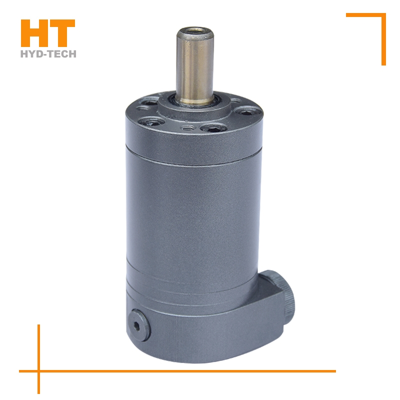
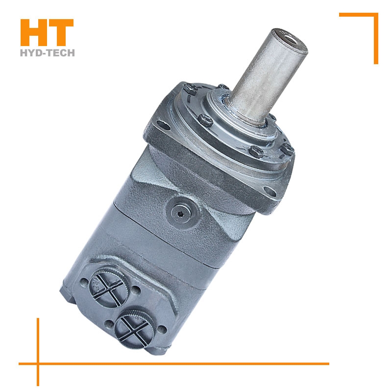
Cycloidal hydraulic motor structure: the internal meshing gear pair consisting of rotor and stator, cycloidal needle wheel, as the meshing pair, has a torque generating part. The stator, together with the spacer and the rear cover, is fixed on the housing to form seven cavities that are only connected with the oil holes on the housing one by one. A distribution mechanism consisting of an oil distribution sleeve and a housing. Two oil distribution sleeves ynz Cycloid hydraulic motor The ring groove is respectively connected with the oil inlet and return ports of the housing, and its longitudinal groove has twelve oil ports, Cycloid hydraulic motor Manufacturer Six oil ports and the oil distribution hole of the housing form the oil distribution link. The splines at both ends of the linkage shaft are respectively connected with the rotor and the output shaft, which is used to transmit torque and ensure that the oil sleeve is synchronized with the output shaft. The function of the output shaft is to output the torque generated by the rotor through the linkage shaft and drive the oil distribution device to rotate synchronously.