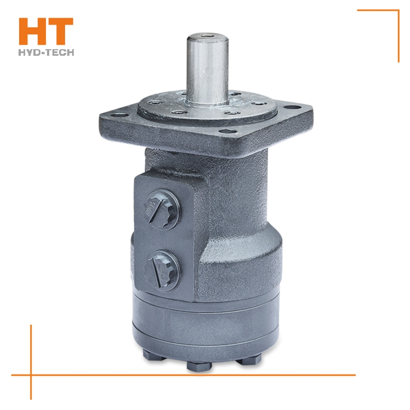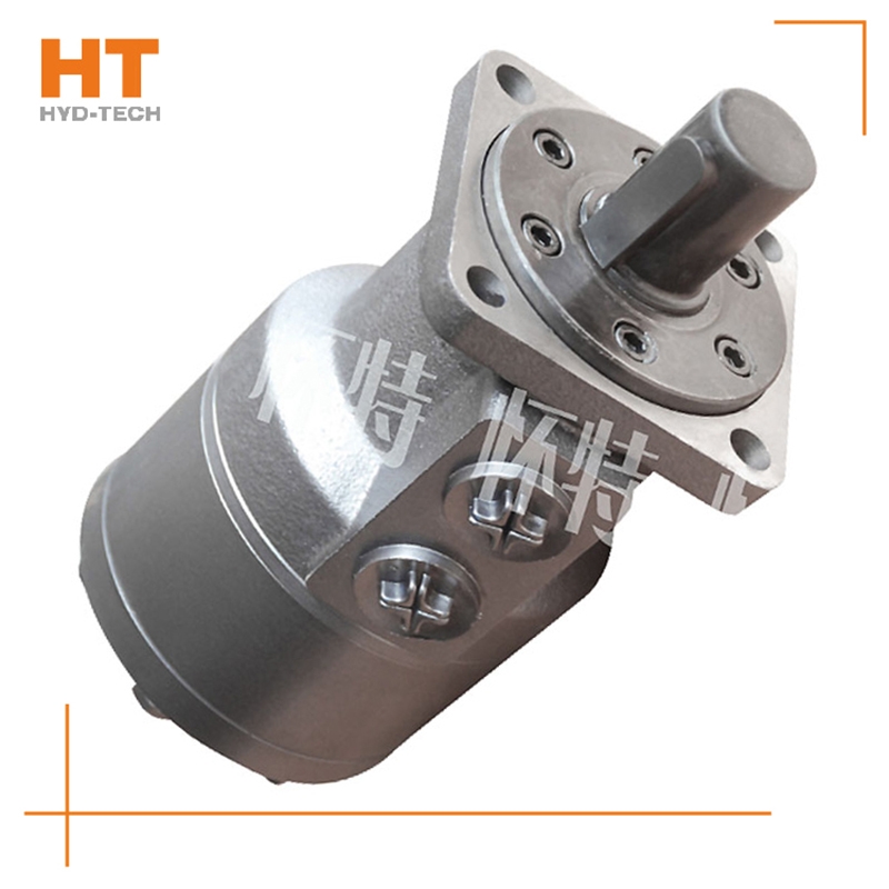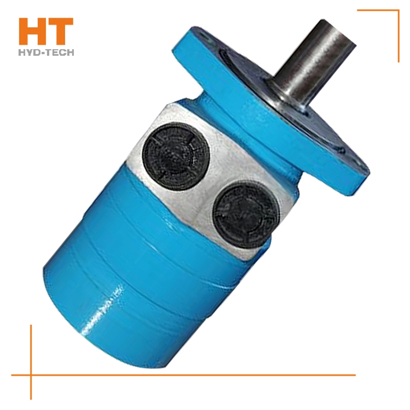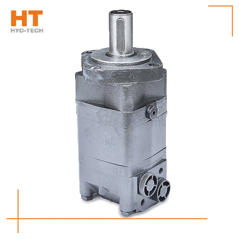
As far as energy conversion is concerned, the hydraulic pump and hydraulic motor are connected as reversible hydraulic components, and the working fluid can be input into any kind of hydraulic pump to make it become a hydraulic motor; On the contrary, when the main shaft of the hydraulic motor rotates under the action of external force Eaton cycloid motor Manufacturer It can also become a hydraulic pump. Because they all have the same basic structural elements, namely sealed and recyclable volume and corresponding distribution mechanism. However, the working environment of hydraulic motor and hydraulic pump is different customized Eaton cycloid motor The performance requirements are also different. Therefore, there are many differences between the hydraulic motor and the hydraulic pump of the same model. The first hydraulic motor should be positive and negative, so its internal structure should be symmetrical; The speed range of the motor must be large enough, especially its minimum stable speed must have certain requirements.

The radial piston hydraulic motor uses a cam ring with a special curve to make each plunger reciprocate several times within one cycle of cylinder block rotation, which is called multi action customized Eaton cycloid motor Internal curve radial plunger hydraulic motor (referred to as internal curve motor) is used. The internal curve motor has the advantages of small size, light weight, radial force balance, small torque ripple, high starting efficiency, stable operation at very low speed, etc. It has been widely used Eaton cycloid motor Manufacturer In marine machinery. Working principle of inner curve motor: the inner wall of the cam ring (housing) is composed of x evenly distributed curved surfaces with the same shape. Each curved surface with the same shape can be divided into two symmetrical sides. The side that allows the plunger set to extend outward is the working section (oil inlet section), and the opposite side is called the oil return section. The number of reciprocating times of each plunger per revolution of the hydraulic motor is equal to the number of curved surfaces of the cam ring x (x is called the number of times of action of the motor).

1) Select the hydraulic pump or motor with good quality and conduct regular maintenance. For example, if the tooth profile accuracy of the gear is low, grind the gear to meet the requirements of the contact surface; 2) If the vane pump has trapped oil, the triangular groove of the oil distributor should be corrected to remove the trapped oil; 3) If the axial clearance of the hydraulic pump is too large and the oil delivery is insufficient Eaton cycloid motor Manufacturer Repair to keep the axial clearance within the allowable range; 4) If the hydraulic pump is not selected correctly, it should be replaced immediately. 3. The reversing valve is improperly adjusted. Improper adjustment of the reversing valve causes the valve core of the reversing valve to move too fast, resulting in reversing shock, noise and vibration. During operation, the valve core branch of hydraulic valve Ningxia Eaton cycloid motor Support on the spring. When its frequency is close to the pulsating frequency of oil delivery rate of hydraulic pump or other vibration sources, vibration and noise will be generated.

Along the revolution direction of the rotor, the volume of the tooth cavity at the front side of the connection between the rotor and the stator becomes smaller, which is an oil discharge cavity, and the volume at the rear side becomes larger. When the connecting line passes through the two tooth roots of the rotor, the oil inlet ends and the largest tooth cavity appears. When the connecting line passes through the two tooth tops of the rotor, the oil drainage ends and the smallest tooth cavity appears. In order to ensure the continuous rotation of the rotor, it is necessary to have the same regular oil distribution mechanism to cooperate with it, so that the tooth cavity at the front side of the connecting pipeline is always connected with the oil drain port, and the rear side is connected with the oil inlet port. As mentioned above, the oil distribution mechanism consists of a housing and an oil distribution sleeve. The 12 longitudinal grooves (x) on the oil distribution sleeve and the 12 intervals formed by the oil distribution groove face the root and top of the rotor through the positioning device, which proves that when the largest and smallest cavities occur, the oil distribution hole of the housing can be closed, thus separating the oil inlet groove and oil outlet groove of the oil distribution sleeve.


![]()

