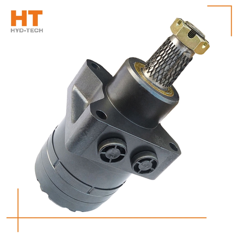
When the main reversing valve of the central closing system and the central closing system is in the neutral position, all oil ports of the reversing valve are closed. If a fixed pump is used for oil supply, the liquid of the hydraulic pump will return to the tank at high pressure through the overflow valve. When the reversing valve is in neutral position, energy transmission starts from the high value, that is, the maximum pressure regulating value of the system. Just reverse OM cycloidal motor Manufacturer , its energy can be used by the actuator. When the reversing valve is in the middle position, it sometimes bears all the pressure of the system, so the internal leakage is greater than that of the open system. Generally, when the doy OM cycloidal motor In this case, the energy consumption of the closed loop is high, but if the intermediate unloading measures are added or the pressure compensated variable pump is used for oil supply, the energy consumption of the closed loop can be greatly reduced. Closed hydraulic systems are used for a variety of equipment.
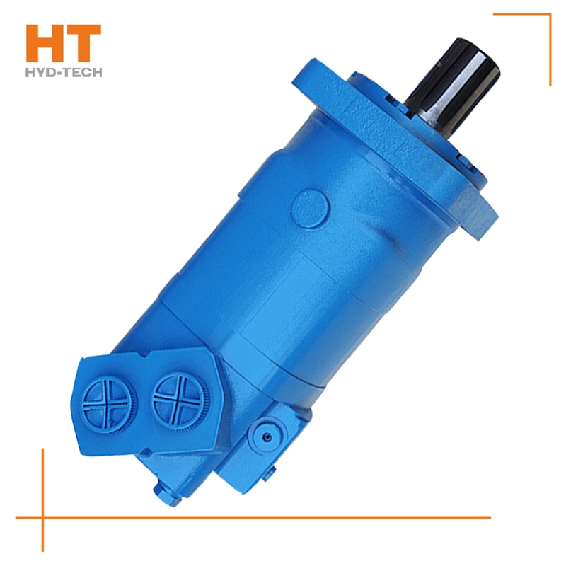
Functions: It is used for the storage, supply and recovery of hydraulic media, the connection between hydraulic components and the transmission of energy carrying hydraulic media, filtering impurities in the hydraulic media, keeping the media required for the normal operation of the system clean, heating or cooling the system, storing and releasing hydraulic energy or absorbing hydraulic pulsation and impact, and displaying the pressure and oil temperature of the system; Hydraulic working medium: various hydraulic oils (fluids), efficacy: as the energy carrying medium of the system, it plays the role of lubrication and cooling while transferring energy. Generally speaking, the hydraulic components that can complete certain specific functions are called hydraulic circuits. In order to meet the working requirements of certain machinery or equipment, the overall structure of several special basic functional circuits connected or combined together is called hydraulic system.
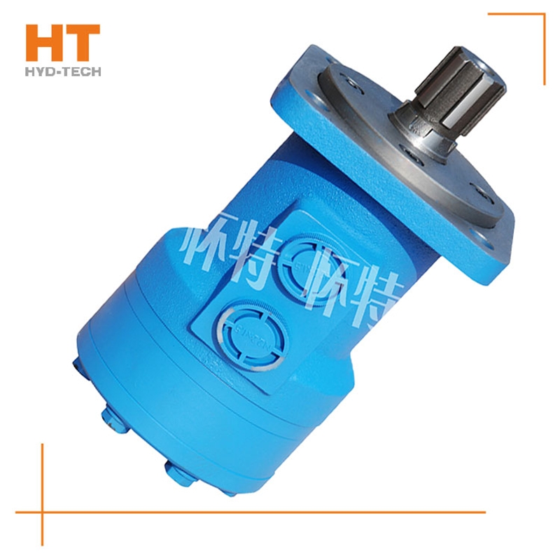
1. Pascal principle: also known as static pressure transmission principle, it refers to the pressure exerted on the static liquid in a closed container is transmitted to all points of the liquid at the same time with equal value. The hyperbolic cosine of 2. The hyperbolic cosine of 2. System pressure: the discharge pressure of the hydraulic pump in the system. The hyperbolic cosine of 3. The hyperbolic cosine of 3. Servo valve and proportional valve: infinitely adjust the output of hydraulic valve, such as pressure, flow and direction, by adjusting the input electrical signal analog quantity. (Servo valve also has pulse want to buy OM cycloidal motor Wide modulation input mode). But the structure of these two valves is completely different. The servo valve controls the work of the torque motor by adjusting the electrical signal to deflect the armature and drive the front valve to work. The front valve control oil enters the main valve and drives the valve core to work. The proportional valve regulates the electrical signal to make the electric iron shift, drive the pilot valve core, drive the control oil generated, and drive the main valve core. The hyperbolic cosine of 4. The hyperbolic cosine of. doy OM cycloidal motor Kinematic viscosity: the ratio of dynamic viscosity μ to the liquid density α. The hyperbolic cosine of 5. The hyperbolic cosine of 5. Fluid power: the force exerted by the flowing liquid on the solid wall to change the flow velocity.
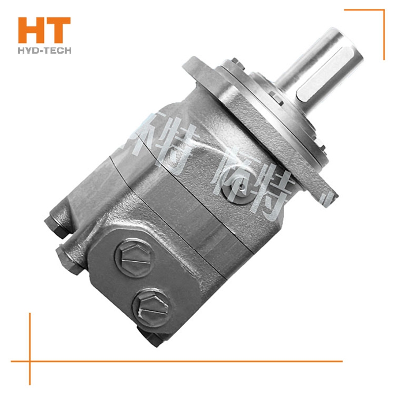
Hydraulic transmission system, the hydraulic transmission system is generally an open loop system without feedback, which mainly transmits power, supplemented by information, and pursues the perfection of transmission characteristics. Hydraulic elements want to buy OM cycloidal motor The characteristics of components and their interactions determine the working characteristics of the system, and its working quality is greatly affected by the changes of working conditions. Hydraulic drive system is widely used. The hydraulic system of most industrial equipment belongs to this category. In the hydraulic control system, servo valves and other electrohydraulic devices are mostly used in the hydraulic control system OM cycloidal motor Manufacturer The control valve constitutes a closed-loop system with feedback, which mainly transmits information, supplemented by power, and pursues the perfection of control performance. The system adds detection feedback, which can combine common components into an accurate control system, and its control quality is less affected by the change of working conditions. Hydraulic control system is widely used in high-precision CNC machine tools, metallurgy, aerospace and other industries.
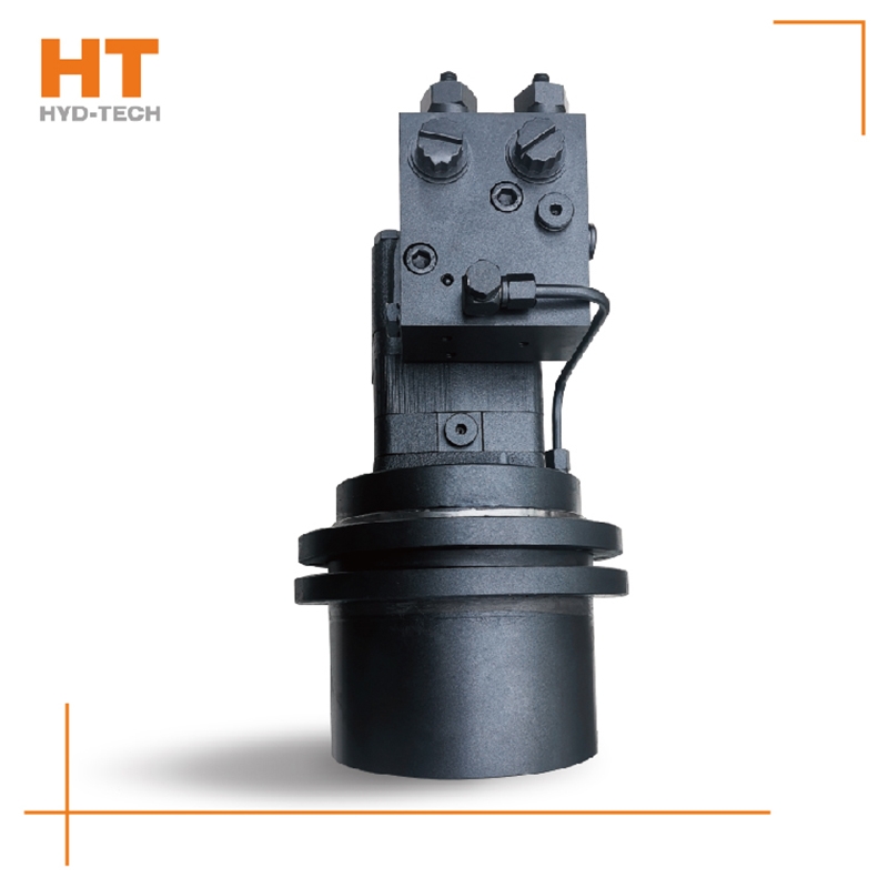
Its basic types are gear type, screw type, vane type and axial plunger type. Its main characteristics are high speed, small moment of inertia, convenient starting and braking, adjustment (speed adjustment and want to buy OM cycloidal motor Reversing) High sensitivity. As the output torque of high-speed hydraulic motor is generally small, it is also called high-speed small torque hydraulic motor. Its basic type is radial plunger type, in addition, there are axial plunger, vane type, gear type and other structural types. Low speed hydraulic motors are mainly characterized by large displacement, large volume and low speed (sometimes OM cycloidal motor Manufacturer It can rotate a few revolutions per minute or even a few revolutions per minute), so it can be directly connected to the working mechanism; It does not need a speed reducer, greatly simplifying the transmission mechanism. Usually, the output torque of low-speed hydraulic motor is large, so it is also called low-speed high torque hydraulic motor.
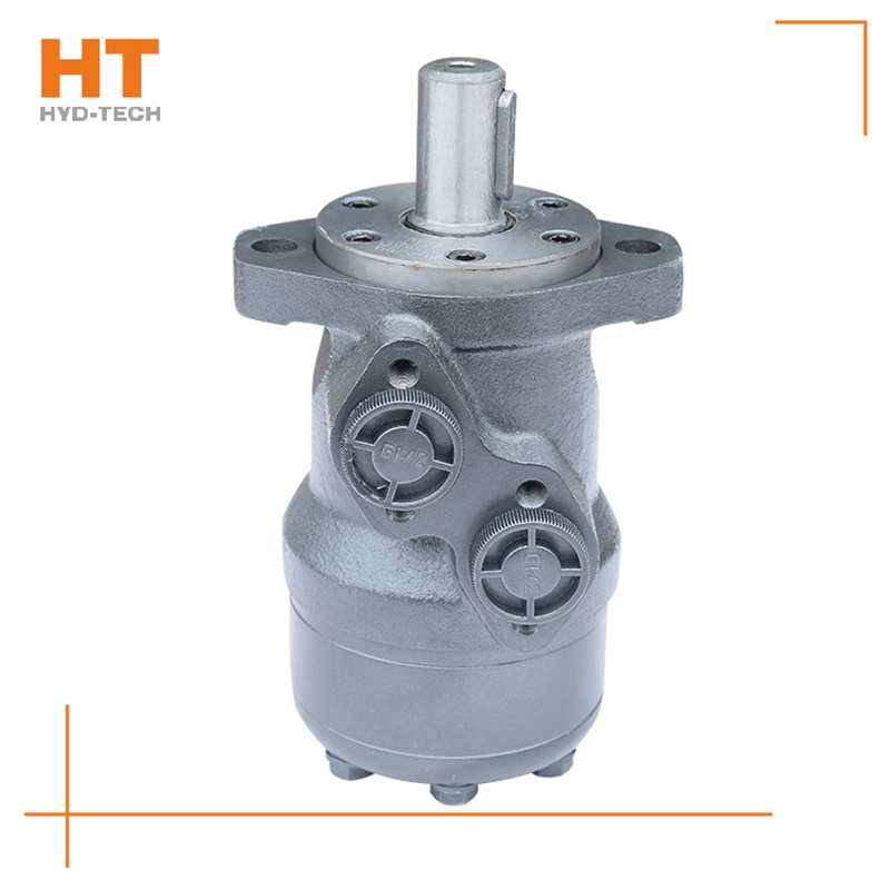
Along the revolution direction of the rotor, the volume of the tooth cavity at the front side of the connection between the rotor and the stator becomes smaller, which is an oil discharge cavity, and the volume at the rear side becomes larger. When the connecting line passes through the two tooth roots of the rotor, the oil inlet ends and the largest tooth cavity appears. When the connecting line passes through the two tooth tops of the rotor, the oil drainage ends and the smallest tooth cavity appears. In order to ensure the continuous rotation of the rotor, it is necessary to have the same regular oil distribution mechanism to cooperate with it, so that the tooth cavity at the front side of the connecting pipeline is always connected with the oil drain port, and the rear side is connected with the oil inlet port. As mentioned above, the oil distribution mechanism consists of a housing and an oil distribution sleeve. The 12 longitudinal grooves (x) on the oil distribution sleeve and the 12 intervals formed by the oil distribution groove face the root and top of the rotor through the positioning device, which proves that when the largest and smallest cavities occur, the oil distribution hole of the housing can be closed, thus separating the oil inlet groove and oil outlet groove of the oil distribution sleeve.


![]()

