The manufacturer of the hydraulic motor has explained to us the relevant knowledge about the speed and low-speed stability of the hydraulic motor. The speed of the hydraulic motor depends on the flow of the supply fluid q and the discharge of the hydraulic motor itself v. The hydraulic motor has internal leakage. Not all the liquid entering the motor drives the hydraulic motor to work. Some of the liquid is lost due to leakage, and the actual speed of the motor is lower than the ideal situation. When the working speed of the hydraulic motor is too low, it cannot maintain a uniform speed, and it stops when entering Jilin Crane cycloid motor The unstable state is a creeping phenomenon. The high-speed hydraulic motor is required to work at a speed below 10r/min and the low-speed high torque hydraulic motor is required to work at a speed below 3r/min. All hydraulic motors can meet the requirements. Generally speaking, the low-speed stability of low-speed large torque hydraulic motors is better than that of high-speed motors. Due to the large emissions and size of the low-speed high torque motor, the sliding speed of the friction pair will not be too low even if the rotation speed is low customized Crane cycloid motor Large emissions, relatively small impact of leakage, large rotation inertia of the motor itself, easy to obtain good low-speed stability.
As the power source and actuator of the hydraulic system, the performance of the hydraulic motor has a great impact on the performance of the entire hydraulic system. Therefore, the importance of studying the hydraulic motor performance test system is customized Crane cycloid motor It is very important that the rise and application of hydraulic testing technology based on virtual instrument has opened up a broad prospect for the performance testing of hydraulic motors. Hydraulic motors are widely used in machine tools, metallurgy, engineering machinery, plastic machinery, agricultural machinery, mining machinery, marine machinery and many other important fields. The performance of the hydraulic motor has a decisive impact on the whole system, and will directly affect the stability of the system. At the same time, the performance of the hydraulic motor will have an impact on the life of the system components and the production efficiency of the system. Jilin manufactor Unexpected failure of hydraulic motor will greatly reduce production efficiency.
The valve control system controls the flow by changing the opening of the valve throttle, thus controlling the speed of the actuator. Usually, the reason for low efficiency is the existence of throttling and overflow losses. Almost all mechanical equipment adopts valve control system. The pump control system can realize the stepless control of speed by changing the displacement of variable displacement pump, or control the flow through the combination of multiple constant displacement pumps to achieve the stepwise control of speed. The reason for high efficiency is that there is no throttling or overflow loss. It is widely used in high power hydraulic devices such as pressure processing machinery and plastic machinery. The actuator control system controls the flow by changing the variable hydraulic motor flow of the actuator, or through the joint work of multiple quantitative hydraulic motors, or by changing the action area of the composite hydraulic cylinder. Similar to the pump control system, this system has high efficiency because it has no throttling and overflow losses. It is suitable for traveling machinery, press and other hydraulic equipment.
Most of its hydraulic system uses working medium, such as hydraulic oil with continuous fluidity, which converts the mechanical energy of the prime mover driving the pump into the pressure energy of the liquid through the hydraulic pump, and sends it to the actuator (hydraulic cylinder, hydraulic motor or swing hydraulic motor) through various control valves, such as pressure, flow, direction, etc., to convert it into mechanical energy to drive the load. This hydraulic system is generally composed of the following parts: power source, actuator, control valve, hydraulic auxiliary device and hydraulic working medium, which play their respective roles: power source: prime mover (motor or internal combustion engine) and hydraulic pump, whose role is to convert the mechanical energy generated by the prime mover into the pressure energy of liquid, and output oil with a certain pressure;
In order to meet the needs of national economic development, hydraulic technology will continue to develop rapidly and be widely used in various industrial sectors. Therefore, vigorously developing the hydraulic machinery industry is also customized Crane cycloid motor In order to revitalize the development of the machinery industry. Based on improving the technical level of basic parts, we will increase the strength of technological innovation, supplemented by policy support, and fundamentally improve the technical level to achieve industrial development. On the other hand, it also shows that the development of hydraulic press in China has entered a new stage, and the development level of heavy equipment represents Crane cycloid motor manufactor The engineering technology level of a country. Therefore, in general, the prospect of hydraulic press in China will be better and better.
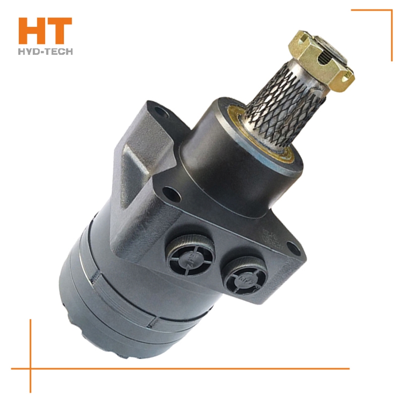
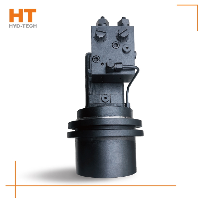
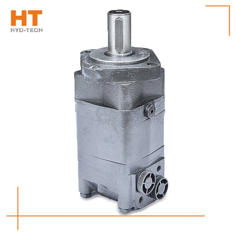
Cycloidal hydraulic motor structure: the internal meshing gear pair consisting of rotor and stator, cycloidal needle wheel, as the meshing pair, has a torque generating part. The stator, together with the spacer and the rear cover, is fixed on the housing to form seven cavities that are only connected with the oil holes on the housing one by one. A distribution mechanism consisting of an oil distribution sleeve and a housing. Two oil distribution sleeves Jilin Crane cycloid motor The ring groove is respectively connected with the oil inlet and return ports of the housing, and its longitudinal groove has twelve oil ports, Crane cycloid motor manufactor Six oil ports and the oil distribution hole of the housing form the oil distribution link. The splines at both ends of the linkage shaft are respectively connected with the rotor and the output shaft, which is used to transmit torque and ensure that the oil sleeve is synchronized with the output shaft. The function of the output shaft is to output the torque generated by the rotor through the linkage shaft and drive the oil distribution device to rotate synchronously.


