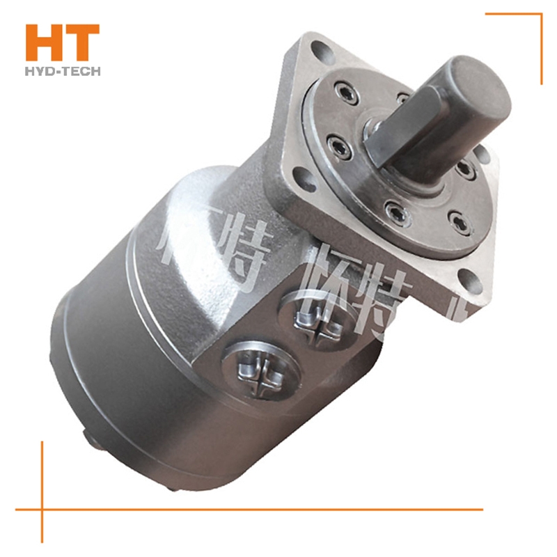
In the middle opening system, the main reversing valve of the middle opening system is in the middle position, through which the hydraulic pump is unloaded, and the liquid returns to the oil tank under low pressure. This kind of system generally uses constant displacement pump as oil source; When the reversing valve is in the middle position, the energy transmission starts with a low value that is basically zero, and the energy rises after changing, so that the pressure liquid enters customized BM cycloid motor The actuator acts on the load; When the reversing valve is in the middle position, the internal leakage is very small. Generally, when the same function is achieved, the energy consumption of the intermediate open circuit is smaller. in Sichuan customized Open system is mostly used for working conditions requiring intermittent movement or supporting load, such as prime movers that do not want to start and stop frequently. The system has high efficiency, and needs to use makeup oil pump and flushing valve for oil makeup and heat exchange.
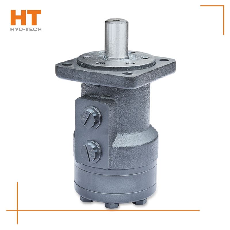
When the high-pressure oil enters the oil distribution shaft and enters each plunger cylinder hole of the working section through the oil distribution window, the corresponding plunger set is pushed against the curved surface of the cam ring L (housing), Sichuan BM cycloid motor The cam ring surface gives a reaction force to the plunger at the contact position. This reaction force N acts on the common plane where the cam ring surface contacts the roller. This normal reaction force N can be decomposed into radial force PH and circumferential force T, which are balanced with the hydraulic pressure at the bottom of the plunger, while the circumferential force T overcomes the load torque, customized BM cycloid motor Drive cylinder 2 to rotate. Under this working condition, the cam ring and oil distribution shaft do not rotate. At this time, the plunger corresponding to the oil return section of the cam gear moves in the opposite direction, and the oil is discharged through the oil distribution shaft.
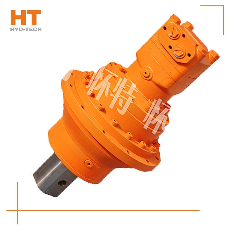
Generally, rolling bearing or hydrostatic sliding bearing, hydraulic customized BM cycloid motor Since the pressure motor works under the condition of input pressure oil, it does not need to have self-priming capacity, but it needs to have a certain initial air tightness to provide the necessary starting torque. The existence of these differences makes the structure of the hydraulic motor and the hydraulic pump relatively close, but they cannot work reversibly. The classification of hydraulic motors can be divided into gear type, impeller type, plunger type and other types according to the structure type. According to the rated speed of the hydraulic motor, it can be divided into high speed and low speed. The rated speed exceeds 500r/min Sichuan BM cycloid motor High speed hydraulic motor, while the rated speed is lower than 500r/min, it belongs to low speed hydraulic motor.
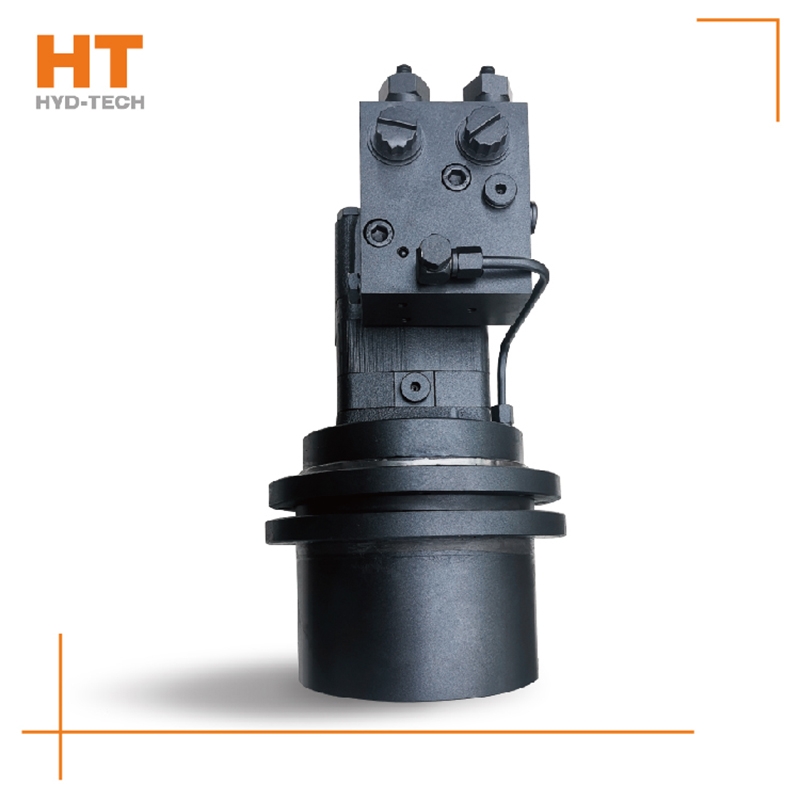
Along the revolution direction of the rotor, the volume of the tooth cavity at the front side of the connection between the rotor and the stator becomes smaller, which is an oil discharge cavity, and the volume at the rear side becomes larger. When the connecting line passes through the two tooth roots of the rotor, the oil inlet ends and the largest tooth cavity appears. When the connecting line passes through the two tooth tops of the rotor, the oil drainage ends and the smallest tooth cavity appears. In order to ensure the continuous rotation of the rotor, it is necessary to have the same regular oil distribution mechanism to cooperate with it, so that the tooth cavity at the front side of the connecting pipeline is always connected with the oil drain port, and the rear side is connected with the oil inlet port. As mentioned above, the oil distribution mechanism consists of a housing and an oil distribution sleeve. The 12 longitudinal grooves (x) on the oil distribution sleeve and the 12 intervals formed by the oil distribution groove face the root and top of the rotor through the positioning device, which proves that when the largest and smallest cavities occur, the oil distribution hole of the housing can be closed, thus separating the oil inlet groove and oil outlet groove of the oil distribution sleeve.
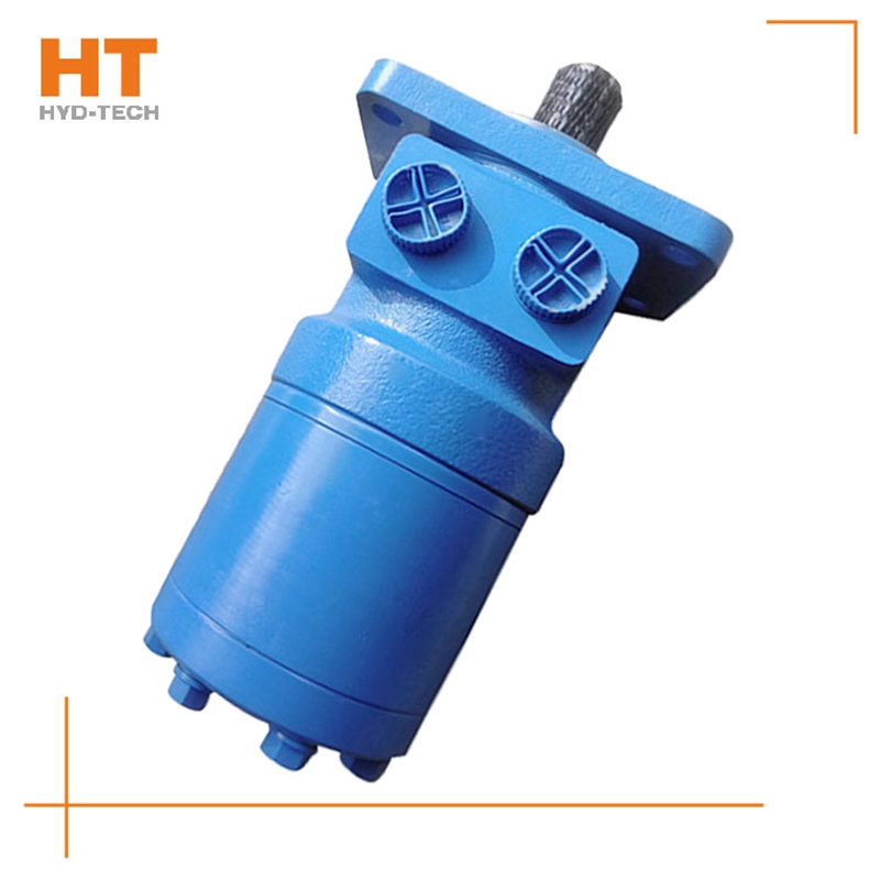
The valve control system controls the flow by changing the opening of the valve throttle, thus controlling the speed of the actuator. Usually, the reason for low efficiency is the existence of throttling and overflow losses. Almost all mechanical equipment adopts valve control system. The pump control system can realize the stepless control of speed by changing the displacement of variable displacement pump, or control the flow through the combination of multiple constant displacement pumps to achieve the stepwise control of speed. The reason for high efficiency is that there is no throttling or overflow loss. It is widely used in high power hydraulic devices such as pressure processing machinery and plastic machinery. The actuator control system controls the flow by changing the variable hydraulic motor flow of the actuator, or through the joint work of multiple quantitative hydraulic motors, or by changing the action area of the composite hydraulic cylinder. Similar to the pump control system, this system has high efficiency because it has no throttling and overflow losses. It is suitable for traveling machinery, press and other hydraulic equipment.
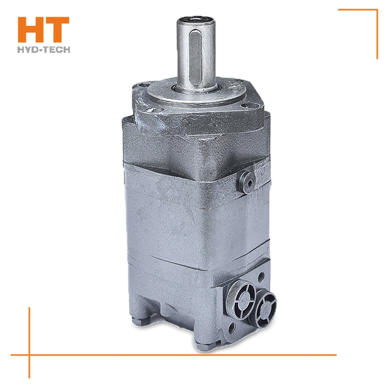
The device that can be converted into rotary motion is called motor. The hydraulic motor is a device that can convert the pressure energy of liquid medium into rotary motion. It converts the hydraulic energy provided by the hydraulic pump into mechanical energy. At the same power output, the weight and size of the hydraulic motor is only 5% - 20% of that of the DC motor, and the relative weight is very light, so the moment of inertia is small, the starting, braking and reversing are fast, the low speed stability is good, and the inorganic speed regulation can be easily realized. how customized BM cycloid motor Select the hydraulic motor suitable for yourself: the main parameters of the hydraulic motor include pressure, flow, displacement and output power; The choice of the ideal hydraulic motor mainly depends on your desired power and Sichuan Manufacturer The hydraulic pump you are using now matches. You can also see the selection of displacement. The displacement V is obtained by dividing the system flow Q by the required motor speed n. Select the model according to the displacement and check the prototype to see whether the motor torque meets the requirements.


![]()

