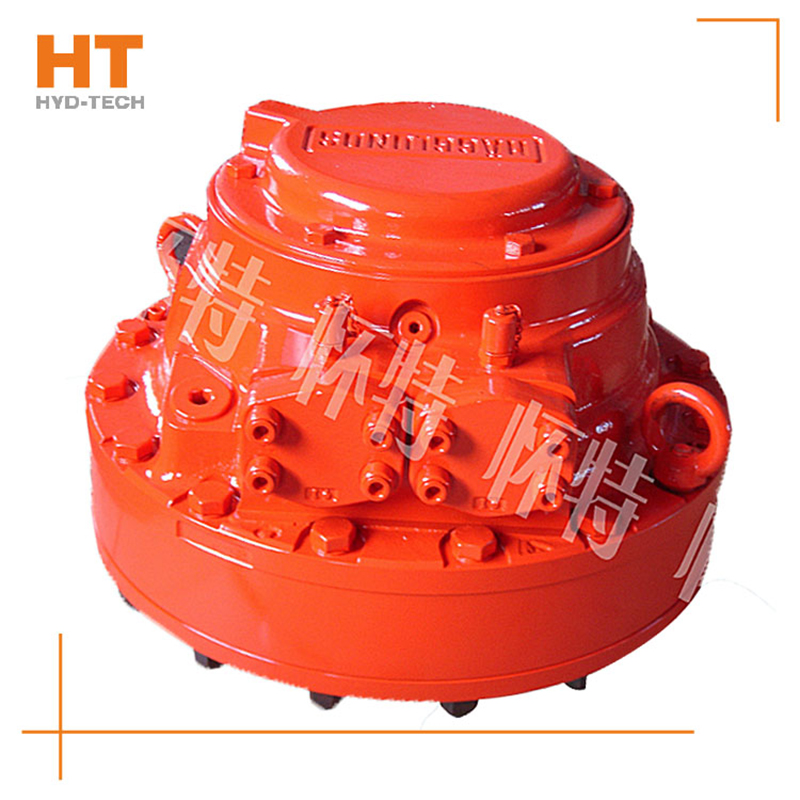
Multi function internal curve Hydraulic motor There are many types of structures. In terms of application methods, there are axle rotation, shell rotation and wheel type hydraulic motor immediately installed in the wheel rim of the wheel. From the perspective of internal structure, there are various forms of plunger components based on different force transmission methods, but the whole process of the key work of the hydraulic motor is the same. Figure 2.27 is taken as an example to show its basic principle.
The hydraulic motor consists of stator 1, also known as camshaft ring Rail car cycloid motor The motor rotor 2, the flow distribution shaft 4 and the plunger set 3 are composed of key components. The inner cavity of the stator 1 is composed of several sections of curved surfaces that are distributed in the same shape. Each curved surface of the same shape can be divided into two sides of symmetry. The side that allows the plunger pair to extend outward is called the middle section for liquid inlet, and the other side that is symmetrical with it is called the middle section for oil discharge, The frequency of each plunger reciprocating in each revolution of the hydraulic motor is equivalent to the number of stator surfaces, which will be called the efficiency frequency of the hydraulic motor; There is a evenly distributed plunger cylinder hole in the axial direction of the motor rotor. At the bottom of each cylinder hole, there is a flow distribution dialog box, and it is interconnected with the flow distribution holes that are matched with the flow distribution shaft 4 of its management center. There is a hole for liquid inlet and oil return in the middle of port shaft 4, and the position of its port dialog box corresponds to the position of the middle section for liquid inlet and oil return on the slide surface. Therefore, there are two evenly distributed port dialog boxes on the port shaft circle. The plunger group 3 is placed in the plunger cylinder hole of the motor rotor 2 with a small gap. The working pressure of the liquid on the plunger is transmitted to the curved surface of the stator through the roller.
The high pressure oil from the hydraulic oil pump goes to the distribution shaft first, and then goes to each plunger cylinder hole in the middle of the working section through the dialog box of the distribution shaft, so that the roller of the corresponding plunger set is pushed against the stator surface. At the contact point, the stator surface gives the plunger set an axial force N, which is effective on the common surface at the contact point between the stator surface and the roller, In this method, the axial force N can be degraded into axial force and circular force, which are in phase with the liquid working pressure at the bottom of the plunger and the centripetal force of the plunger set, and the resulting driver torque will break away from the load torque to make the motor rotor 2 rotate. The fitness exercise performed by the plunger is a compound fitness exercise, that is, it rotates with the motor rotor 2 and repeatedly moves in the plunger cylinder hole of the motor rotor. The stator and flow distribution shaft are not rotating. The plunger matched with the oil return section of the stator surface performs the opposite direction fitness exercise. According to the oil return of the distribution shaft, when the plunger set 3 is connected to the oil return section through the middle section of the stator surface, the oil and oil return safety channels provided are closed.
If the oil inlet and outlet directions of the hydraulic motor are interchanged, the hydraulic motor will turn over; If the rotating shaft is fixed, the stator, port shaft and housing will rotate, which is generally referred to as the working condition of the shell rotor and becomes a wheel motor.
In addition to the above typical low-speed large torque motors Cycloid hydraulic motor The hydraulic motor is located between the fast motor and the low-speed motor. I won't explain it too much here.


![]()

